800-543-9038 USA 866-805-7089 CANADA 203-791-8396 LATIN AMERICA
2
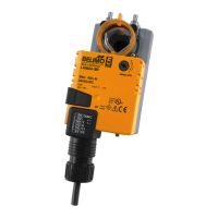
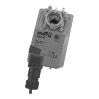
LMB
X
24-
R
-T
Proportional, Non-Sprin
Return, 24 V, for 2 to 10 VDC or 4 to 20 mA
orque min. 45 in-lb for control of damper surfaces up to 11 sq ft
l
LMB24-SR/LMX24-SR LMB24-SR.1 (bulk
LMB24-SR-T/LMX24-SR-T LMB24-SR-T.1 (bulk
Applicatio
or proportional modulation of dampers in HVAC systems. Actuator sizin
should be
one in accordance with the dam
er manufacturer’s s
ecifications.
he actuator is mounted directly to a damper shaft from 1
4” up to 5
8” in diameter
y means of its universal clamp. Shafts up to 3/4” diameter can be accommodated by
n accessor
clam
.
he actuator operates in response to a 2 to 10 VDC, or with the addition of
00
resistor, a 4 to 20 mA control in
ut from an electronic controller or
ositioner.
2 to 10 VDC feedback si
nal is provided for position indication or master-slave
pplications
eratio
he actuator is not
rovided with and does not re
uire an
limit switches, but is
electronically protected a
ainst overload. The anti-rotation strap supplied with the
ctuator will prevent lateral movement.
he LMB series provides 95° o
rotation and a visual indicator indicates position o
the
ctuator.
en reac
ng t
e
amper or actuator en
pos
t
on, t
e actuator
utomat
ca
y stops.
e
ears can
e manua
y
sen
a
e
w
t
a
utton on t
e
c
ua
or cover.
he LMB24-SR… actuators use a sensorless brushless DC motor, which is controlled
y an Application
pecific Integrated
ircuit (A
I
). The A
I
monitors and controls
the actuator’s rotation and provides a digital rotation sensing (DRS) function to prevent
ama
e to the actuator in a stall condition. Power consumption is reduced in holdin
mode
dd-on auxiliary switches or
eedback potentiometers are easily
astened directly onto
the actuator body
or signaling and switching
unctions
Dimensions (Inches [mm])
1.85” [47]
2.34” [59.4]
2.6” [66]
4.57” [116]
3.47” [88]
3.7” [94]
0.86” [22]
2” [50.8]
1/4” to 3/4” [6 to 20]
5/16” to 3/4” [8 to 26]
To center of
mounting slot.
Technical Data LMB(X)24-SR(-T)
ower su
24 VA
± 2
H
24 VD
± 1
ower consumptio
1.5 W (0.4 W)
Trans
ormer sizin
3 VA
Class 2 power source
lectrical connectio
3 ft, 18 GA plenum rated cabl
1
2” conduit connecto
protected NEMA 2 (IP54
3 ft [1m] 10 ft [3m] 16 ft [5m]
Overload protectio
electronic throu
hout 0 to 95° rotation
Operatin
ran
e
2 to 10 VDC, 4 to 20 m
nput
mpe
anc
100
0.1 m
, 500
eedback out
ut
2 to 10 VDC
max 0.5 mA
n
le o
rotatio
max. 95°, ad
ustable with mechanical stop
orqu
45
n-
5
m
Direction o
rotatio
revers
e w
t
sw
tc
actuator will move
=CCW with decreasin
control si
nal
10 to 2V
=CW with decreasin
control si
nal
10 to 2V
osition indicatio
reflective visual indicator
snap-on
anua
overr
externa
pus
utto
unn
ng t
m
95 seconds, constant independent o
loa
umidit
5 to 95% RH non condensin
EN 60730-1
m
ent temperatur
-22°F to 122°F [-30°
to 50°
]
torage temperatur
-40°F to 176°F [-40°
to 80°
]
ous
n
2,
54,
enc
osure type 2
ousing materia
L
4-
VA
gency
st
ngs
cULus acc. to UL 60730-1A
-2-14,
CAN/CSA E60730-1:02,
E acc. to 2004
108
EE
and 2006
95
E
v
<35
ervicin
m
int
n
n
r
uality standar
I
1
e
1.7
s
0.5
LMB(X)24-
R-T
tr
nn
t
screw terminal
for 26 to 14
A wire
ous
n
unprotected
NEMA 1
IP20
protected (NEMA 2
IP20) use Z
-T
† Rated Impulse Volta
e 800V, Type of action 1, Control Pollution De
ree 3
40024 - 05/10 - Subject to change. © Belimo Aircontrols (USA), Inc.