Diagnostics
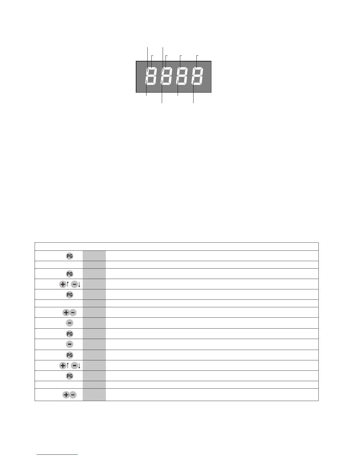
In the event of malfunctions, by pressing key + or - the status of all inputs (limit switches, control and safety) can be displayed. One
segment of the display is linked to each input. In the event of failure it switches on according to the following scheme.
Error messages
The control unit checks the correct operation of the safety devices. In case of failure, the following messages may appear on the
display:
ERR1 Error, check photocells at PHOT O input.
ERR2 Error, check photocells at PHOT C input.
ERR3 Error, ENCODER/ check fuse F3
ERR4 Error, TRIAC
Fuses
F1 Protection fuse of transformer
F2 Output protection fuse of accessories and signals
F3 Output protection fuse for motor and blinker
Example of programming
Let us suppose it is necessary to:
- set an automatic closing time (TCA) of 100s
- activate pre-blinking
Perform the operations described below step by step:
Step Press Display Notes
1
PAR
First menu
2
TCA
First function of the first menu
3
040
Value currently set for the function selected
4
100
Set the desired value with the <+> and <-> keys
5
PRG
The value is programmed
TCA
When programming has been made, the display goes to the function just set
6
PAR
Press <+> and <-> simultaneously to go to the higher menu
7
Log
Second menu
8
TCA
First function of the second menu
9
Pre
Press <-> several times to select PRE logic
10
OFF
Value currently set for the function selected
11
ON
Set the desired value with the <+> and <-> keys
12
PRG
The value is programmed
Pre
When programming has been made, the display goes to the function just set
13
PAR
Press <+> and <-> simultaneously to go to the higher menu and quit programming or wait
30s.