6
B. WALL MOUNTING – using the wall mounting plate
(sold separately)
1. PREPARATION
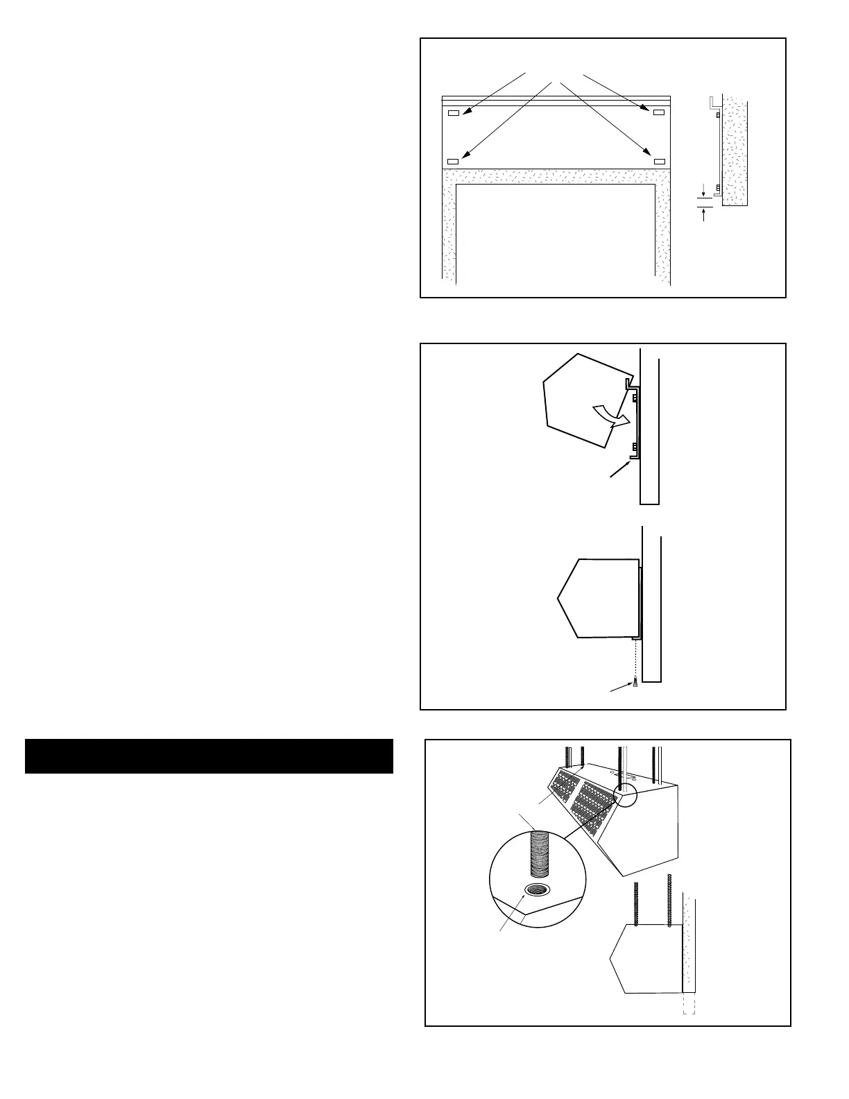
a. Position and center the mounting plate over
the door opening. The mounting plate must
be positioned with the “Z” lip on top. Drill
mounting holes on the mounting plate. See
Figure 6.
b. Mark the wall in the center of each mounting
plate hole. The wall must provide sucient
support for the air curtain. The mounting
hardware (supplied by others) must be
capable of supporting a minimum of three
times the net weight of the air curtain. See
Weight Chart, Table 1 or Table 2. If the
location of the marks on the wall do not
provide suitable support, mark and drill
additional holes.
c. Drill the four holes as marked on the wall and
attach the mounting plate with anchors (if
used) and the four mounting screws (provided
by others).
2. ATTACHING THE AIR CURTAIN
TO THE MOUNTING PLATE
a. Raise the air curtain over the door (air
discharge nozzle facing down) and on to the
mounting plate. First, tilt the unit upward
matching the rectangular openings to the “Z”
lip on the mounting plate. See Figure 7.
b. Lower the air curtain into place, allowing it to
rest on the lower lip of the mounting plate.
c. After the air curtain is securely attached to the
mounting plate, re-install the two (2) locking
screws at the bottom corners. See Figure 7.
IV. SUSPENDED MOUNTING
A. For top mounting using suspension rods, four (4) factory
installed 1/4” threaded inserts are located in the top of the
air curtain. See Figure 8.
B. Install 1/4” threaded rods, or other suitable hardware at
a location with sucient support for the air curtain. The
mounting hardware (supplied by others) must be capable
of supporting a minimum of three times the net weight of
the air curtain. See Weight Chart, Table 1 or Table 2.
C. Attach threaded rods, or other suitable hardware to the top
mounted threaded inserts.
D. Proceed to Section V – Electrical Connections
FIGURE 8 - Suspended Mounting
1" max.
Doorway Opening
Recommended Mounting
Plate Holes
Doorway
Opening
FIGURE 6 - Positioning of Mounting Plate
FIGURE 7
Locking Screws
Mounting Plate
Lower Lip
Suspension Rods
1/4”
Threaded Insert
Side View
 Loading...