3. Name and function of each part
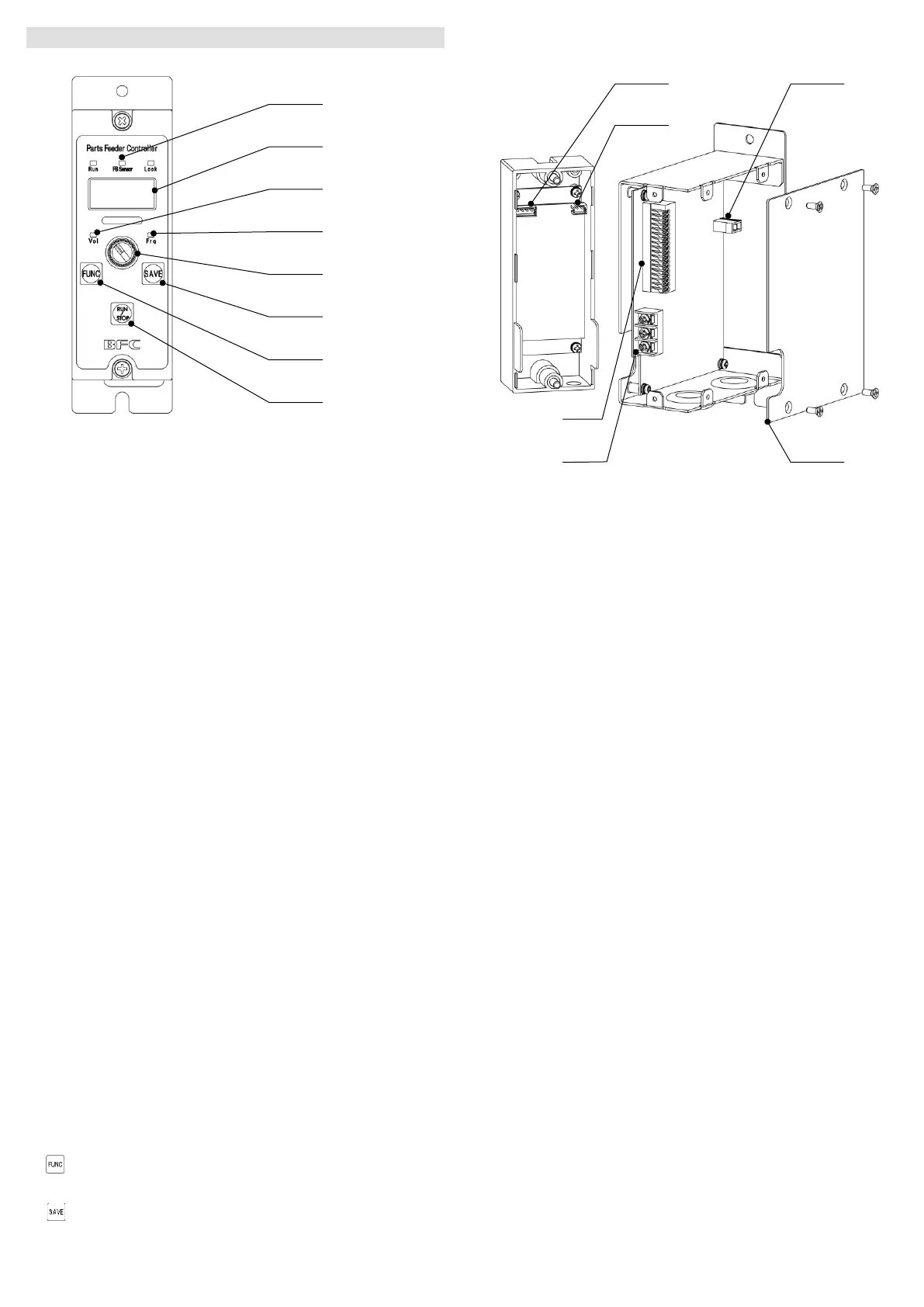
3-1 Operation panel
1 State indicator
Indicates the state of the equipment.
Run ON --- The vibrator is running.
Blink --- The vibrator is at standby.
OFF --- Stopped by RUN/STOP button.
FB sensor ON --- The feedback function is enabled.
Blink --- The feedback sensor is connected.
OFF --- The feedback sensor is not connected.
Lock ON --- The key lock function is enabled.
OFF --- The key lock function is disabled.
2 Set value display
Set value, etc. are displayed.
3 Voltage lamp
Vol Turns ON while the output voltage set value is displayed.
4 Frequency lamp
Frq Turns ON while the output frequency set value is displayed.
5 Encoder
Used to change the set value.
6 SAVE button
Used to save the set value.
7 FUNCTION button
Used to call out the function menu.
8 RUN/STOP button
Used to manually run/stop.
*Special operations
Hold down Used to switch between basic setting and advanced
setting.
Hold down Used to switch between ON/OFF of key lock function.
3-2 Internal area
A Feedback sensor connector
Connector for connecting the feedback sensor
B Analog input connector
Connecting analog voltage signal for adjustment of output voltage setting
value
C Vibrator connector
Connecting piezoelectric vibrator is connected
D Side panel
E Control I/O
Terminal block for signals input to/output from the main unit
F Power input terminal block
Connecting input power line
 Loading...