3-3 Terminal block
Control I/O
Input/output terminal block for control
1 Input signal terminal
Used to externally control the vibrator operation
IN0 Operation signal 1
IN1 Operation signal 2
IN2 Pattern No. selection signal 1
IN3 Pattern No. selection signal 2
COM.i Common for input signal terminal
2 Output signal terminal
Used to externally output the operation state of the vibrator
OUT0 Operation synchronization signal 1
OUT1 Operation synchronization signal 2 (equipped with
off-delay function)
OUT2 Workpiece shortage signal (AFC-20H only)
OUT3 Alarm signal
COM.O Common for output signal terminal
3.4 Service power supply terminal
24 VDC can be supplied to sensors used for parts feeder full control, etc.
Supply capacity 24 VDC 100 mA
24V 24 VDC
GND 0 V
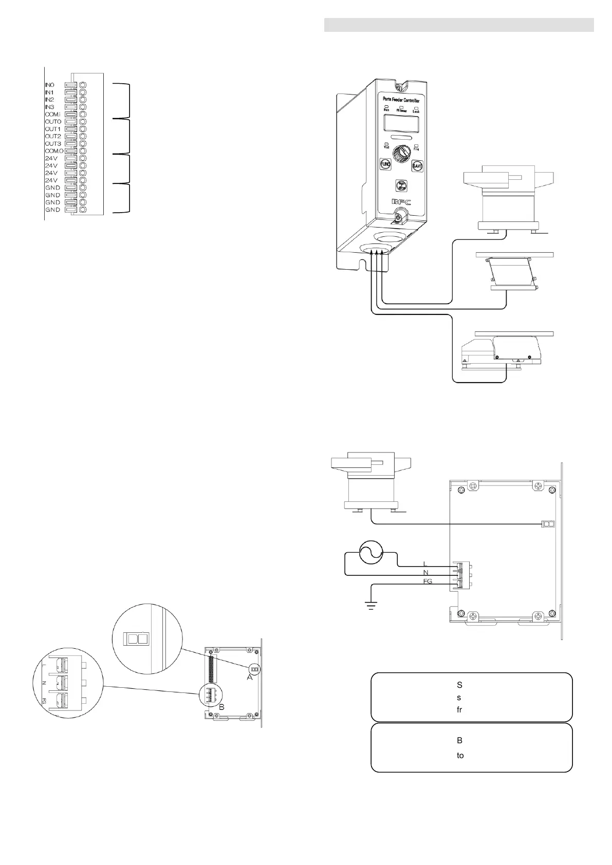
Connection of power supply, vibrator
Power supply input terminal block, vibrator connector
Part A Vibrator connector: Connect the vibrator
Part B Power supply input terminal: Supply 85 to 265 VAC 50 Hz/60 Hz
4. Wiring
4-1 Connection with vibrator
Connect the piezoelectric feeder to the output terminal of the equipment.
*Connect one piezoelectric feeder to each of the equipment.
4-2 Connection with input/output lines
Remove front unit of the equipment and the side cover, and connect the
power supply to the power supply input terminal block and the vibrator to
the vibrator connector.
supply before removing the
! Warning
Be sure to connect a ground
to the “FG” terminal.
!
 Loading...