5. Preparation
Check again whether wiring is done correctly before installing the
front unit.
Turn ON the power supply.
After initialization of the system, the output voltage set value is
indicated on the set value display.
6. Let’s use
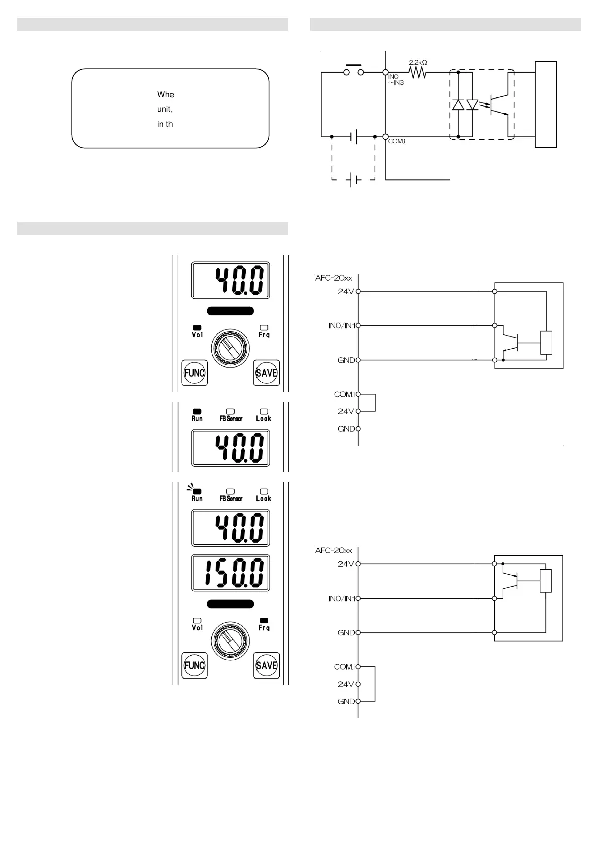
Let’s move the vibrator.
6-1 Press the FUNCTION key to turn
ON the voltage lamp and change
the output voltage set value to 40.0
by using an encoder.
Press the SAVE key to determine
the change.
6-2 If Run is OFF, press the
RUN/STOP button to turn it ON.
If Run is blinking, check the
operation signal.
The vibrator changes to operation
state if the operation signal is input.
6-3 Press the FUNCTION key to turn
ON the frequency lamp and adjust
the vibration to an area near the
strongest state (resonance point)
by using an encoder.
After adjustment, press the SAVE
key to save the change.
*The resonance point is between
75 to 250 Hz, although the value
varies depending on the load.
*If the vibration is weak and the area where it becomes strong is
difficult to find out, increase the output voltage set value.
6-4 After determining the optimal frequency, change the voltage set value
and obtain an appropriate vibration.
7. Connection with external devices
7-1 Input circuit diagram
IN0, IN1, IN2, IN3
Rated input voltage 24 VDC 15 mA
Example of connection
Connection of NPN output sensor
1 Short-circuit COM.i and 24 V of the equipment.
2 Connect 24 VDC of the sensor to 24 V of the equipment.
3 Connect the sensor output to IN0/IN1 of the equipment.
4 Connect 0 V of the sensor to GND of the equipment.
Connection of PNP output sensor
1 Short-circuit COM.i and GND of the equipment.
2 Connect 24 VDC of the sensor to 24 V of the equipment.
3 Connect the sensor output to IN0/IN1 of the equipment.
4 Connect 0 V of the sensor to GND of the equipment.
When installing the front
unit, do not tuck in or push
in the flat cable forcibly.
! Caution
Power supply to input circuit
 Loading...