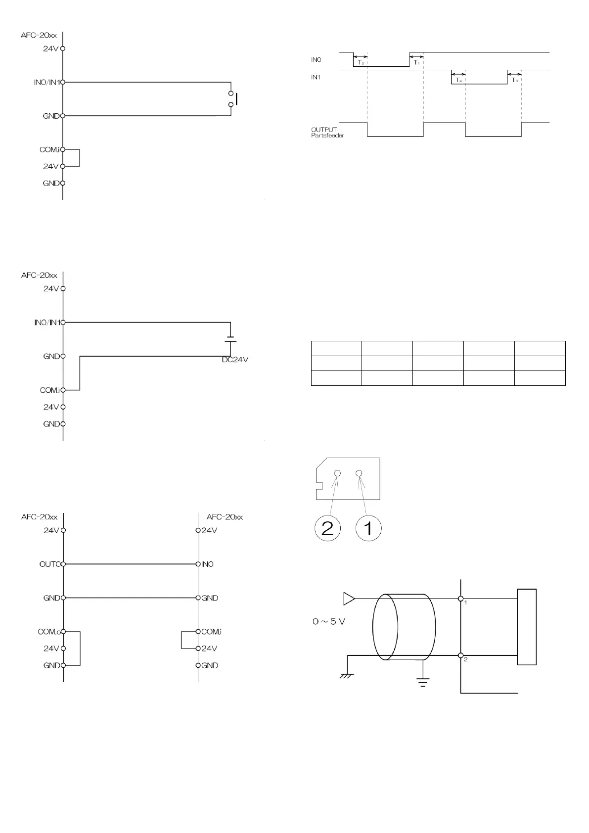
Connection of relay
1 Short-circuit COM.i and 24 V of the equipment.
2 Connect the contact point of the relay to GND and IN0/IN1 of the
equipment.
Connection of voltage signals
1 Connect voltage signal + to COM.i of the equipment.
2 Connect voltage signal - to IN0/IN1 of the equipment.
Linkage of controller
The slave unit is operated when the master unit is operated.
1 Short-circuit COM.o and GND of the master unit.
2 Short-circuit COM.i and 24 V of the slave unit.
3 Connect OUT0 of the master unit to IN0 of the slave unit.
4 Connect GND of the master unit to GND of the slave unit.
*Full sensor, etc. can be connected to IN1 of the slave unit.
*When connecting a sensor to IN1 of the slave unit, set the advanced
setting to “nor.” If connection is not done, set the advanced setting to “inv”.
7-2 Terminals for IN0/IN1 operation signals
Operation/stop of the vibrator can be done by input to IN0 or IN1.
*Operation/stop logics for the input signal can be changed by the
advanced setting.
*Operation/stop of the vibrator can be controlled by setting ON/OFF delay
timer for the input signal by the advanced setting.
7-3 Input terminal for switching IN2/IN3 pattern No.
The amplitude setting can be switched by input to IN2 or IN3.
How to use
Select “Pt” in “input terminal detailed setting” for the advanced setting.
Four patterns of voltage and frequency can be set for input to IN2 or IN3.
*Currently used setting No. is displayed in “display of currently used
extensions” in the basic setting.
7-4 B analog input connector
The output voltage set value for AFC-20HG can be changed by analog
voltage signal connected to the connector.
[1] Analog voltage input
[2] Common terminal
Molex 5267-02A connector pin layout
Applicable housing Molex 5264-02
Applicable terminal Molex 5263
Wiring of analog voltage input
How to use
Select “AnLG” in “input terminal detailed setting” for the advanced setting.
 Loading...