7-5 A feedback sensor connector
The vibrator is operated at a constant amplitude using the feedback sensor
connected to the connector.
Special feedback sensor PHA-03-C15 (1.5 m)
PHA-03-C35 (3.5 m)
Sensor connection cable PHA-03-CC (0.5 m)
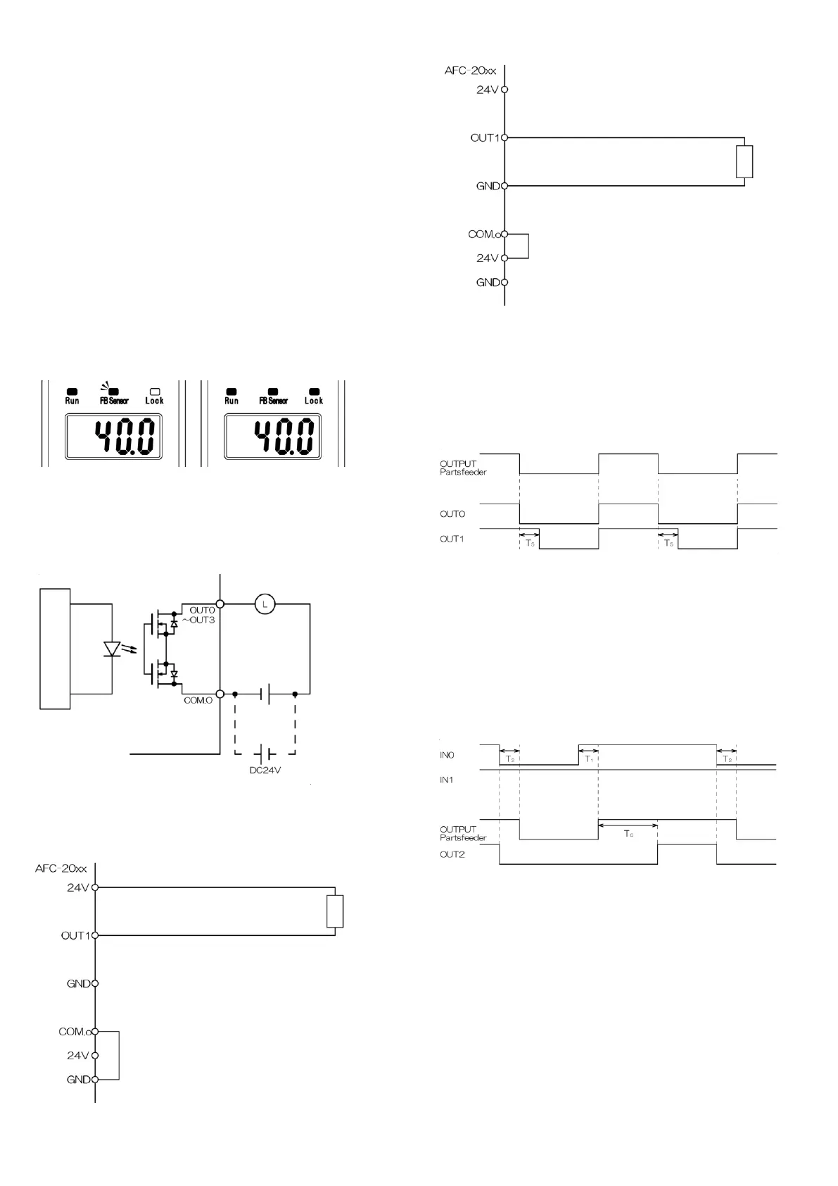
When the feedback sensor is installed to the controller, state indicator FB
sensor on the operation panel blinks.
When the SAVE key is held down while the vibrator is running and FB
sensor is blinking, operation lock is activated and feedback operation is
started.
State indicator FB sensor is ON during feedback operation.
During feedback operation, the voltage set value is changed automatically
by the controller to maintain the amplitude at a certain level in line with the
vibrator load.
Normal operation Feedback operation
When the SAVE key is held down during feedback operation, operation
lock is canceled and normal operation is started.
7-6 Output circuit diagram
OUT0, OUT1, OUT2, OUT3
Rated load 30 VDC 100 mA
Example of connection
Connection of electromagnetic valve load, etc. to the output (NPN)
1 Short-circuit COM.o and 24 V of the equipment.
2 Connect the load to 24 V and OUT1 of the equipment.
Connection of electromagnetic valve load, etc. to the output (PNP)
1 Short-circuit COM.o and 24 V of the equipment.
2 Connect the load to 24 V and OUT1 of the equipment.
7-7 OUT0/OUT1 operation synchronization output
terminal
Load connected to the terminal can be driven in synchronization with
vibrator operation.
*Logic of the output signal can be changed by the advanced setting.
*Stop can be delayed if OFF delay timer is set for the output signal by the
advanced setting (OUT1 only).
7-8 OUT2 workpiece shortage signal output
terminal
The signal is output when shortage of workpieces in the parts feeder is
detected by the full sensor.
*Logic of the output signal can be changed by the advanced setting.
*The function is for AFC-20HG only.
7-9 OUT3 alarm signal output terminal
Responding to controller errors, error indications are displayed on the set
value display and alarm signals are output.
Error indication
“Err2” Overcurrent is flowing to the output to the vibrator.
“Err3” Signals are not input from the feedback sensor.
*In case of errors, remove the cause and then turn ON the power supply to
the controller.
 Loading...