15
www.bindicator.com
LVP180914 Rev. D
FAILSAFE SELECTION
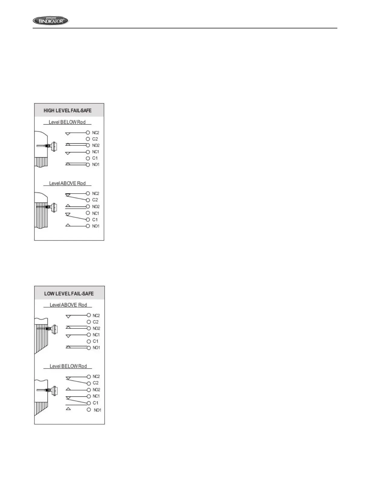
The LP II is factory set for high level fail-safe operation. The Fail-Safe is controlled by SW1, position 1 on Standard units;
SW5, position 1 for Advanced units. Refer to Figure 13 to determine the Fail-Safe mode that suits your application.
Figure 13. Fail-Safe Operation
HIGH LEVEL FAILSAFE OPERATION DEFAULT
DIP Switch Settings
• STANDARD: SW1-1 is OFF
• ADVANCED: SW5-1 is OFF
Alarm State (material above the rod)
• Main Relay is de-energized
Relay NC contacts are closed
Relay NO contacts are open
• Alarm LED is ON
Non-Alarm State (material below the rod)
• Main Relay is energized
Relay NC contacts are open
Relay NO contacts are closed
• Alarm LED is OFF
Note: If the electrical power fails, the main relay turns OFF, giving the same indication
as if material is above the rod.
LOW LEVEL FAILSAFE OPERATION
DIP Switch Settings
• STANDARD: SW1-1 is ON
• ADVANCED: SW5-1 is ON
Alarm State (material below the rod)
• Main Relay is de-energized
Relay NC contacts are closed
Relay NO contacts are open
• Alarm LED is ON
Non-Alarm State (material above the rod)
• Main Relay is energized
Relay NC contacts are open
Relay NO contacts are closed
• Alarm LED is OFF
Note: If the electrical power fails, the main relay turns OFF, giving the same indication
as if material is below the rod.
 Loading...