u If the supply cord is damaged, it must be replaced by the
manufacturer or an authorised BLACK+DECKER Service
Centre in order to avoid a hazard.
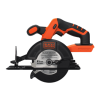
Features
This tool includes some or all of the following features.
1. Main handle
2. Lock-off button
3. On/Off trigger
4. Battery (may not be included)
5. Shoe
6. Depth adjustment knob
7. Secondary handle
8. Upper Guard
9. Bevel adjustment scale
10. Blade
11. Lower blade guard
12. Depth adjustment scale
13. Locking tool
14. Dust extraction port
15. Bevel adjustment knob
16. Spindle lock
Assembly
Warning! Before attempting any of the following operations,
make sure that the tool is switched off and unplugged and that
the saw blade has stopped.
To install the battery pack (g. A)
u Insert battery pack into tool as shown in gure A. Ensure
battery pack is fully seated and fully latched into position.
To Remove the battery pack (g. B)
u Depress the battery release button as shown in gure B.
and pull battery pack out of tool.
Supporting large panels/Securing workpiece (g. C)
u Support large panels to minimize the risk of blade
pinching and kickback. Large panels tend to sag under
their own weight as shown in gure C.
u Supports must be placed under the panel on both
sides, near the line of cut and near the edge of the
panel gure C.
u Never hold piece being cut in your hands or across
your leg gure D.
u Secure the workpiece to a stable platform as shown in
gure E. It is important to support the work properly to
minimize body exposure, blade binding, or loss of control.
Cutting Depth Adjustment - (g. F - G)
u The depth of cut should be set according to the
thickness of the workpiece.
u Loosen the depth adjustment knob (6) to unlock the
saw shoe (5) as shown in figure F.
u Move the saw shoe into the desired position. The
corresponding depth of cut can be read from the scale
(12).
u Set depth adjustment of saw such that one tooth (10)
of the blade projects below the workpiece (16) as
shown in figure G.
u Tighten the knob to lock the saw shoe in place.
Bevel Angle Adjustment - (g. K)
This tool can be set to bevel angles between 0° and 50°.
u Loosen the bevel adjustment knob (14) to unlock the
saw shoe (5).
u Move the saw shoe (5) into the desired position. The
corresponding bevel angle can be read from the scale (9).
u Tighten the bevel adjustment knob (15) to lock the
saw shoe in place.
u Conrm the accuracy of the setting by checking the
bevel angle of an actual cut on a scrap piece of material.
Shoe Adjustment For 90° Cuts
The shoe (5) has been set by the factory to assure that
the blade is perpendicular to the shoe at 0° bevel setting.
IF REALIGNMENT IS NEEDED:
u Adjust the saw to 0° bevel.
u Retract blade guard (11).
u Loosen bevel adjustment knob (15). Place a square
against the blade (10) and shoe (5) to adjust the 90° set-
ting.
u Loosen jam nut (16) and move the adjustment screw (19)
(inset gure H) so that the shoe will stop at the proper
angle. Retighten jam nut against the shoe while holding
adjustment screw in position.
u Conrm the accuracy of the setting by checking the
squareness of an actual cut on a scrap piece of material.
Attaching and Removing the Blade (g. I - J)
u Retract lower guard and assemble blade (10) and clamp
washer (20) as shown in gure I.
u Depress the spindle lock (16) while turning the blade
bolt (21) with the locking tool (13) until the blade lock
engages and the blade stops rotating.
NOTE: Locking tool is stored on the saw as shown
in gure J.
u Tighten the blade bolt securely with the locking tool.
NOTE: Bolt has a left-handed thread. To loosen, turn
clockwise. To tighten, turn counterclockwise.
NOTE: Never engage the blade lock while the saw is
running, or engage in an effort to stop the tool.
Never turn the tool on while the blade lock is engaged.
Serious damage to your saw will result.

 Loading...