2 | Bus address settings
3 | Installation
After you set the address switches for the proper address, install the
module in the enclosure, and then wire it to the control panel and other
devices.
NOTICE!
Remove all power (AC and battery) before making any
connections. Failure to do so might result in personal injury
and/or equipment damage.
3.1 | Mount the module in the enclosure
Mount the module into the enclosure’s 3-hole mounting
pattern using the supplied mounting screws and mounting
bracket. Refer to Figure 3.1.
3
1
2
Figure 3.1: Mounting the module in the enclosure
Callout ― Description
1 ― Module with mounting bracket installed
2 ― Enclosure
3 ― Mounting screws (3)
3.2 | Mount and wire the tamper switch
For instructions on this optional switch, refer to the
Conettix Ethernet
Communication Module (B426) Installation and Operation Guide (P/N:
F01U266226) and the
EZTS Cover and Wall Tamper Switch Installation
Guide (P/N: F01U003734).
3.3 | Wire to an SDI or SDI2 control panel
When you wire a B426 to an SDI or SDI2 control panel, you can use
either the module’s terminal strip labeled R, Y, G, B (PWR, A, B, COM)
or the module’s interconnect wiring connectors (wire included).
Figure 1.1 indicates the location of both the terminal strip and the
interconnect connectors on the module. Refer to Figure 3.2.
NOTICE!
Use either the terminal strip wiring or interconnect wiring
connector to the control panel. Do not use both. When
connecting multiple modules, you can combine terminal strip
and interconnect wiring connectors in series.
1 | Overview
NOTICE!
The module must be mounted in either the control panel’s
enclosure or in a listed enclosure such as the D8103
Universal Enclosure.
NOTICE!
Before browsing to a new settings page, you must click
OK to save edited values.
Set the address switches per the control panel conguration. If
multiple B426 modules reside on the same system, each B426 module
must have a unique address.
Callout ― Description
1 ― SDI2 control panel. For SDI control panels, wire R, Y, G, B to
the SDI bus.
2 ― Interconnect wiring connectors
3 ― To Ethernet network
4 ― Terminal strip wiring
5 ― Interconnect cable (P/N: F01U079745) (included)
6 ― Option bus control panel
3.4 | Wire to an option bus control panel
Run the wires from the module to the data bus terminals on the
compatible control panel. Refer to Figure 3.2.
Figure 3.2: Wiring to the control panel (GV4 Series and FPD-7024
4 | Conguration
Congure the B426 using one of the methods described in this section
for your control panel type.
NOTICE!
By default, when connecting a eld replacement B426 to an
existing SDI2 Control Panel, the panel overrides the module
settings. To keep custom module settings when you connect
a module to a congured SDI2 control panel, you must
disable Panel Programming using web-based conguration,
prior to connecting to the SDI2 bus.
An SDI2-compatible control panel automatically congures a newly
connected module.
1. Ensure the B426 is new, or defaulted to the factory settings.
2. Set the address switch to the correct address for the control panel
(SDI2 control panels use address 1 or 2).
3. Program the control panel communication settings using RPS or the
keypad.
4. Connect the module to the control panel bus and apply power.
NOTICE!
Before proceeding, ensure that the web browser is not
congured to use a proxy server. Refer to the browser’s
online help for instructions on disabling proxy service.
4.1 | Congure an SDI2 control panel
4.2 | Congure an SDI, option bus control panel
Congure for an SDI or option bus control panel using one of the
methods described in this section.
4.2.1 | Plug and Play conguration
When installing under the following conditions, the B426 needs no
further conguration:
– DHCP is available on your network.
– AES encryption is not required.
– Default B426 port settings (UDP on Port 7700) are permitted by
the network administrator.
4.2.2 | Web-based conguration
For installations where additional non-default settings are required, a
web-based conguration menu is available.
Determine the module’s hostname or IP address by one of the following
methods:
– Locate the IP address in the table on the DHCP server
(networked modules).
– Use Auto IP to direct connect from your PC to the B426.
Within 60 seconds, the B426 temporarily assumes address
169.254.1.1 for conguration. (
Refer to the Conettix Ethernet
Communication Module Installation and Operation Guide
for more
information on using these methods.)
To use web-based conguration (B426 conguration web pages):
1. Open an internet browser (Microsoft Internet Explorer 6 or
higher, or Mozilla Firefox 3 or higher) and type in the B426’s IP
address. The B426’s login page opens.
2. Enter the default password: B42V2 and click Login. The Device
Information home page opens.
3. Browse to the desired settings page and congure the
parameters.
4. Click OK and then click Save & Execute to save and apply all
changes to the device.
control panel shown)
NOTICE!
The module reads the address switch setting only during
power up. If you change the switches after you apply power
to the module, you must cycle the power to the module in
order for the new setting to be enabled.
One address switch determines the address for the B426 Conettix
Ethernet Communication Module. The control panel uses the address
for communications. Use a slotted screwdriver to set the address
switches.
The B426 address switch provides a ones value for the module’s
address. Figure 2.1 shows the address switch setting for address 1.
Refer to Table 2.1 for panel-specic settings.
Figure 2.1: Address switch
Table 2.1: Address switch settings
Control
panels
Switch
position
B426
address
Bus type Function
For web-based
conguration
0 Congu-
rable
Any Web-based
conguration
GV4 and B
Series
1 1 SDI2 Automation,
Remote
Programming,
or
Reporting
GV4 Series 2 2
GV4/GV3/,
GV2 Series, G
Series v6.3 or
higher
3 80 SDI Automation
4 88 Remote
programming or
Reporting
GV4 and GV3
Series
5 92
FPD-7024 9 250 Option
The B426 Ethernet Communication Module is a four-wire powered SDI,
SDI2, or Option bus device that provides two-way communication with
compatible control panels over IPv4 or IPv6 Ethernet networks.
The B426 on-board switch determines the bus address of the device.
Conguration of the B426 is performed through the B426 conguration
web pages. On SDI2 control panels, conguration can also be done on
the keypad or through Remote Programming Software (RPS).
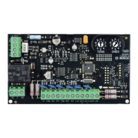
Figure 1.1: Board overview
Callout ― Description
1 ― Ethernet RJ-45 port
2 ― Yellow LINK LED
3 ― Green 100MB LED
4 ― Address switch
5 ― Heartbeat LED (blue)
6 ― Data bus communication LEDs (TX and RX)
7 ― SDI2 terminal strip
(to control panel or additional modules)
8 ― SDI2 interconnect wiring connectors
(to control panel or additional modules)
9 ― Tamper switch connector