6
Subject to change without prior notice Revised 05-12
6 720 220 048
CE Series
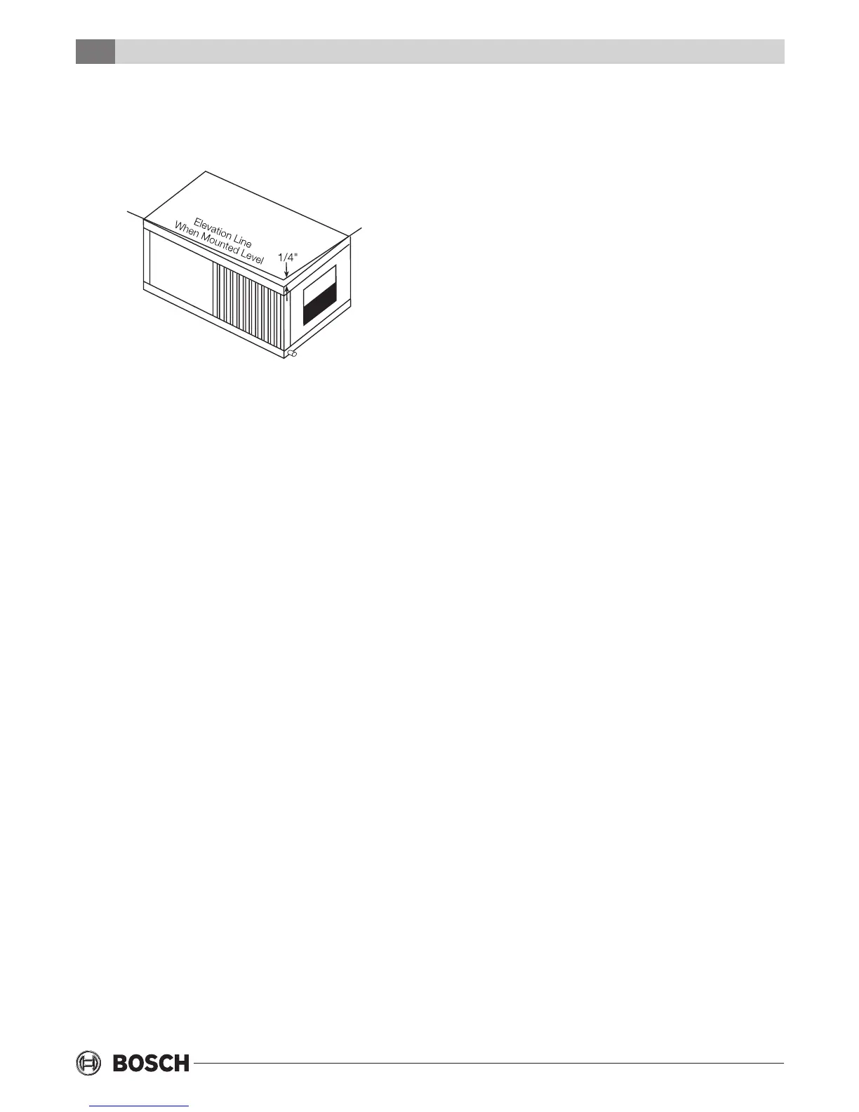
The horizontal unit should be pitched approximately
1/4” towards the drain in both directions, to
facilitate condensate removal. (See Figure #4)
DUCT SYSTEM
A supply air outlet collar and return air duct ange
are provided on all units to facilitate duct
connections. Refer to the individual data
specication sheet for physical dimensions of the
collar and ange.
A exible connector is recommended for supply and
return air duct connections on metal duct systems.
All metal ducting should be insulated with a
minimum of one inch duct insulation to avoid heat
loss or gain and prevent condensate forming during
the cooling operation. Application of the unit to
uninsulated duct work is not recommended as the
unit’s performance will be adversely affected. Do not
connect discharge ducts directly to the blower
outlet. The factory provided air lter must be
removed when using a lter back return air grill. The
factory lter should be left in place on a free return
system.
If the unit will be installed in a new installation which
includes new duct work, the installation should be
designed using current ASHRAE procedures for duct
sizing. If the unit is to be connected to existing
ductwork, a check should be made to assure that the
duct system has the capacity to handle the air
required for the unit application. If the duct system
is too small, larger ductwork should be installed.
Check for existing leaks and repair.
The duct system and all diffusers should be sized to
handle the designed air ow quietly. To maximize
sound attenuation of the unit blower, the supply and
Figure #4
return air plenums should be insulated. There should
be no direct straight air path thru the return air grille
into the heat pump. The return air inlet to the heat
pump must have at least one 90 degree turn away
from the space return air grille. If air noise or
excessive air ow are a problem, the blower speed
can be changed to a lower speed to reduce air ow.
(Refer to ECM motor interface board section in this
manual and Figure #7)
PIPING
Supply and return piping must be as large as the
unit connections on the heat pump (larger on long
runs). Never use exible hoses of a smaller inside
diameter than that of the uid connections on the
unit. CE units are supplied with either a copper or
optional cupro-nickel condenser. Copper is
adequate for ground water that is not high in
mineral content. Should your well driller express
concern regarding the quality of the well water
available or should any known hazards exist in your
area, we recommend proper testing to assure the
well water quality is suitable for use with water
source equipment. In conditions anticipating
moderate scale formation or in brackish water a
cupro-nickel heat exchanger is recommended.
Both the supply and discharge water lines will sweat
if subjected to low water temperature. These lines
should be insulated to prevent damage from
condensation.
All manual ow valves used in the system must be
ball valves. Globe and gate valves must not be used
due to high pressure drop and poor throttling
characteristics. Never exceed the recommended
water ow rates as serious damage or erosion of the
water to refrigerant heat exchanger could occur.
Always check carefully for water leaks and repair
appropriately. Units are equipped with female pipe
thread ttings. Consult the specication sheets for
sizes. Teon tape sealer should be used when
connecting water piping connections to the units to
insure against leaks and possible heat exchanger
fouling. Do not overtighten the connections. Flexible
hoses should be used between the unit and the rigid
system to avoid possible vibration. Ball valves should
be installed in the supply and return lines for unit
isolation and unit water ow balancing.
Duct System
 Loading...