2 | EP Series
EP Series
8733953041 (2019/01)
Subject to change without prior notice
CONTENTS
Model Nomenclature..........................................................3
Initial Inspection................................................................4
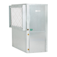
General Description...........................................................4
Moving and Storage...........................................................5
Location............................................................................5
INSTALLATION ..................................................................5
MOUNTING VERTICALLY...............................................5
MOUNTING HORIZONTALY............................................5
Hanging Bracket Kit........................................................... 6
Installation instructions ................................................6
CONDENSATE DRAIN .........................................................7
Duct System......................................................................7
Piping ...............................................................................8
Electrical .......................................................................... 8
ECM INTERFACE BOARD...............................................9
Thermostat Connections....................................................9
Safety Devices and the UPM Controller .............................11
Electronic Thermostat Installation.....................................13
UPM Sequence of Operation.............................................14
Electric Heater Package Option ........................................15
Water Quality...................................................................15
Water Quality
Table........................................................................16
Heat Recovery Package ...................................................17
Typical Connection Piping (HRP)..................................17
Water Tank Preparation: .............................................17
HR Water Piping ........................................................ 17
Water Tank Refill............................................................. 18
Initial Start-Up...........................................................18
Hot Gas Reheat (HGRH)..............................................18
Sequence of Operation ....................................................19
Cooling Mode............................................................19
Heating Mode............................................................19
Application considerations...............................................19
Well Water Systems ...................................................19
Installation of Pressure Regulating Valves.........................20
Cooling Tower/Boiler Systems.......................................... 20
Geothermal (Earth-Coupled) Systems ..........................22
System Checkout.............................................................23
Unit Start-up ...................................................................23
Maintenance................................................................... 24
Unit Check-Out Sheet ...................................................... 25
Customer Data.......................................................... 25
Unit Nameplate Data.................................................. 25
Operating Conditions................................................. 25
Auxiliary Heat ........................................................... 25
troubleshooting .............................................................. 26
Standard Motor PSC
Table...............................................................................29
Constant CFM Motors
Table..............................................................................30
Water side Pressure Drop
Table...............................................................................32
Air Temperature Rise/Fall.................................................33
Refrigerant Pressure Ranges.............................................34
Unit Dimensions...............................................................35
Vertical
Dimensions...............................................................35
Horizontal
Dimensions................................................................36
Wiring diagrams.............................................................. 37
Notes ............................................................................. 43
Key to symbols and safety instructions
Key to symbols
Warnings
The following keywords are defined and can be used in
this document:
• NOTE indicates a situation that could result in
damage to property or equipment.
• CAUTION indicates a situation that could result in
minor to medium injury.
• WARNING indicates a situation that could result in
severe injury or death.
• DANGER indicates a situation that will result in
severe injury or death.
Warnings in this document are identified by a warning
triangle printed against a grey background.
Keywords at the start of a warning indicate the type and
seriousness of the ensuing risk if measures to prevent
the risk s are not taken.
 Loading...