Gas type conversion
Greenstar FS/Combi FS – 6 720 810 590 (2020/04)
64
▶ Press and hold the emissions test button C until it lights up.
The display shows the supply temperature alternating with =
maximum set output in heating mode.
▶ Briefly press the emissions test button C.
The display shows the supply temperature in alternation with =
maximum nominal output.
▶ Measure the CO
2
or O
2
level and the CO content of the flue gas (
Chapter 13).
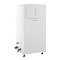
▶ ‘On the gas throttle, break the seal at the slot and remove the cap.
Fig. 76 Remove seal from the gas throttle
▶ Adjust the gas throttle to match the CO
2
or O
2
level for maximum
nominal output according to table 33.
Fig. 77 Set CO2 or O2 level for maximum nominal output
Table 33 CO
2
or O
2
values at maximum and minimum nominal output
▶ Briefly press the emissions test button C.
The display shows the supply temperature in alternation with =
minimum nominal output.
▶ Measure the CO
2
or O
2
level and the CO content of the flue gas
(Chapter 13).
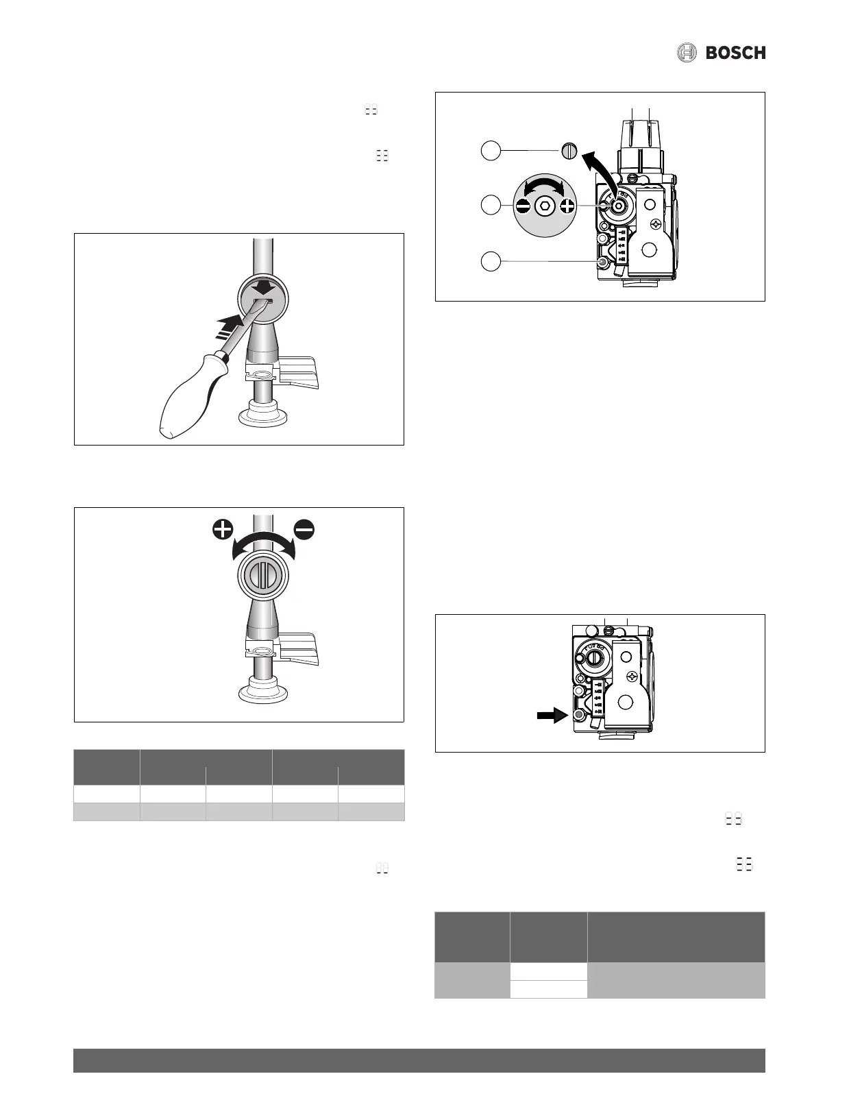
▶ Remove the sealed screw ( Fig. 78, [3]) from gas valve adjustment
screw (Fig. 78, [2]) and set CO
2
or O
2
level for minimum nominal
output.
Fig. 78 Set CO
2
or O
2
level for minimum nominal output
[1] Gas inlet pressure test point
[2] Minimum adjustment screw
[3] Minimum adjustment screw cover
▶ Re-check settings at maximum and minimum nominal output and
readjust if necessary.
▶ Repeatedly press the emissions test button C until the light goes out.
The display returns to the supply temperature.
▶ Record the CO
2
or O
2
levels and the CO content of the flue gas in the
commissioning log.
▶ Reinstall the screw (Fig. 78, [3]) to cover the gas valve adjustment
screw.
▶ Remove flue gas probe and refit the plug into the flue gas test port and
tighten to secure.
12.3 Dynamic gas pressure test
▶ Switch the appliance OFF and close the gas shut-off valve.
▶ Loosen the screw in the test port for gas inlet pressure (. Fig. 78, [1])
and connect a pressure gauge ( Fig. 79).
Fig. 79 Dynamic gas pressure test port
▶ Turn on the gas cock and switch the appliance ON.
▶ Press and hold the emissions test button C until it lights up.
The display shows the supply temperature alternating with =
maximum set output in heating mode.
▶ Briefly press the emissions test button C.
The display shows the supply temperature in alternation with =
maximum nominal output.
▶ Check the required inlet gas pressure according to table 34.
Table 34 Inlet gas pressure
Maximum nominal output Minimum nominal output
Gas type CO
2
O
2
CO
2
O
2
NG 9.4% 4.0% 8.6% 5.5%
LPG Propane 11.0% 4.2% 10.4% 5.1%
1 .
2 .
6 7 2 0 6 1 2 6 5 9 - 3 7 . 1 R
6 7 2 0 6 1 2 6 5 9 - 3 8 . 1 R
Nominal
pressure
Permissible pressure range for
maximum nominal output
Gas type “W.C. (mbar) “W.C. (mbar)
NG 7 (17.4) 3.5 - 10.5 (8.7 - 26.1)
LPG (propane) 11 (27.4) 8 - 13 (19.9 - 32.3)
6 720 641 933-81.1O
1
3
2
6 720 614 090-34.2O
 Loading...