Bosch Security Systems | 2003-09 | 3922 988 92883en
Plena Mixer Amplifier | Installation and Operating Manual | en | 9
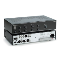
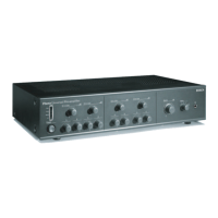
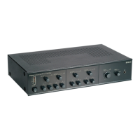
1.2 Controls and connections (rear)
Figure 1.3
1 Chime ON/OFF switch
2 Priority microphone input (5-pole DIN/balanced
with Phantom power)
3 Input 1 microphone input (6.3 mm phono jack/
balanced with Phantom power)
4 Microphone input (XLR/balanced with Phantom
power in microphone mode)
5 Microphone input (6.3 mm phono jack/balanced)
6 Input Mic./Line switch
7 Emergency connection input terminals
8 Emergency volume pre-set
9 CD input (2x phono connectors)
10 Tape input (2x phono connectors)
11 Auxiliary input (2x phono connectors)
12 Line output (XLR)
13 Tape output (2x phono connectors)
14 Insertion input/output (2x phono connectors)
15 Loudspeaker output terminals and 24 Vdc power
supply terminals
16 Mains connector (3-pole)
17 Earth connection screw
18 Mains fuse
LBB1903 T1A (230 Vac) / T2A (115 Vac)
LBB1906 T1.6A (230 Vac) / T3.15A (115 Vac)
LBB1912 T2.5A (230 Vac) / T5A (115 Vac)
LBB1914 T2.5A (230 Vac) / T5A (115 Vac)
19 Mains voltage 115/230 V switch
31
1
45
L
R
CD Aux Line Out 1V
Mic/Line Mic/Line
Inc
Out
In
0
0
Chime
Tel/Emer.
2
1
GND
2
3
1
++GND
2
3
2 3 4
230V115 V
Call/Mix
24VDCIn
Call Only Mix Only
100V 0 70V 0 100/70V 0 100/70 V 080
7
12
4 43 5 5 4 5 15
15
Only for LB B1914/10
16 186 6
8 9 10 11 12 13 14 19
17
24VDCIn
Call/Mix
Zone 1 Zone 2
Call Only Mix Only
100/70V/8 0 100/70V 0 100/70V 0 100/70V 0 100/70V 0
About the mixer amplifier
 Loading...