6 720 862 440 (2016/04) Heat Pump Mini VRF Outdoor Unit
4 | OPERATING CONDITIONS
Display function
Follow the function below (12/14/16 kW).
Normal display Display “--”
â
á
Operating mode
(0—Stanby; 2—Cooling;
3—Heating; 4—Forced cooling)
The last fault or protection code (if
there is no fault or protection code
it will display “nn”)
â
á
Operating fan speed
(0—Power off)
The quantity of indoor units
operating
â
á
The total capacity requirements of
the interior units
Total quantity of interior units
â
á
The capacity requirements of the
external unit
T2 average temperature
â
á
T3 pipework temperature Actual voltage AD value
â
á
T4 ambient temperature Actual current value
â
á
T5 actual discharge temperature.
If this temperature is over 100
degrees, then the display will only
show a rounded
down figure
PMV opening
á
The surface temperature of the
cooling fin
á
Follow the function below (8/10.5/18 kW).
Normal display Display “--”
â
á
Operating mode
(0—Stanby; 2—Cooling;
3—Heating; 4—Forced cooling)
The last fault or protection code (if
there is no fault or protection code
it will display “nn”)
â
á
Operating fan speed
(0—Power off)
Version of the program
â
á
The total capacity requirements of
the interior unit
Priority mode
(Reserved)
á
â
Model (8 KW: 8,10 KW: 10,
18 KW:18)
The capacity requirements of the
revised external unit
á
â
The quantity of indoor units
operating
T3 pipework temperature
á
â
T2 average temperature
T4 ambient temperature
á
â
Actual voltage AD value
T5 actual discharge temperature.
If this temperature is over 100
degrees, then the display will only
show a rounded down figure
á
Actual current value
á
â
PMV opening
á
The surface temperature of the
cooling fin
NOTE
• On completion of installing the air conditioning unit, ensure the
electrical power supply is on to the unit for the minimum of 12hrs
prior to operation. Failure to do so, may result in product failure.
Should the units electrical power supply be interrupted for a
period of more than 24hrs, then the above process will have to
be repeated.
• Pay attention not to block the air inlet and outlet. Blockages may
decrease the efficiency of the unit or shut the unit down via it‘s
protection devices.
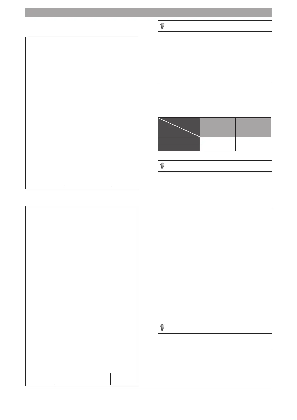
3. OPERATING CONDITIONS
See the table below for safe and effective use of the system. Maximum and
minimum temperatures are displayed.
Temperature
Mode
Outdoor
temperature
Room
temperature
Cooling operation -15 °C~43 °C -17 °C~32 °C
Heating operating -15 °C~27 °C ≤27 °C
NOTE
1 If air conditioning unit is used outside the above conditions, it may
cause the unit to function abnormally.
2 The units can produce condense water when the humidity is high.
3 Optimum performance will be achieved within these operating
temperatures.
4. OPERATION AND PERFORMANCE
4.1 Protection Devices
The protection devices will stop the unit from running when an error is
detected.
This protection device will stop the unit automatically. When a protection
device is activated, the running indicator flashes. The protection device may
have been activated as a result of the following circumstances.
The protection devices may be activated in following conditions:
■ Cooling Operation
• The air inlet or air outlet on the outdoor unit is blocked.
• Strong winds are continuously blowing on the air outlet.
■ Heating Operation
• The indoor unit filters are blocked.
• The air outlet on the indoor unit is blocked.
NOTE
Do not attempt to re-activate the electrical power supply to the unit
via the protection device until the problem has been solved.
4.2 Electrical power to the unit is interrupted
• Should the electrical power supply be interrupted, all operation of the
unit will stop. Isolate the main electrical supply to the unit until the
electrical power supply has returned and stabilised.
• When the electrical power supply is re-established, the controller will
flash and will begin to initialise.
 Loading...