Electrical | 31SM Series Heat Pump
6 720 220 406 (2015/02)Revised 02-15
The unit is provided with a concentric knock-out
for attaching common trade sizes of conduit, route
power supply wiring through this opening. Always
connect the ground lead to the grounding lug
provided in the control box and power leads to the
line side of compressor contactor as indicated on
the wiring diagram (Figures#113 through #117
Pg#65 through Pg#66).
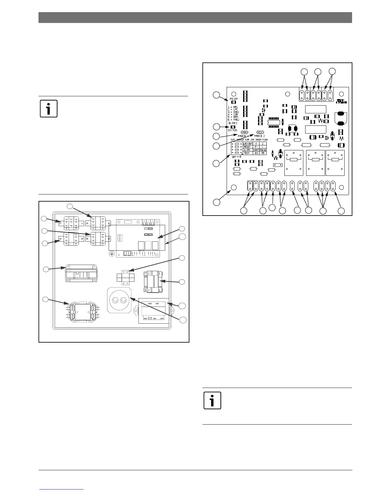
Figure # 97
[1] Compressor contactor
[2] Comfort Alert Module (Option)
[3] Emergency Relay (Option)
[4] Second Stage Relay
[5] Hot Gas Reheat Relay (Option)
[6] Cooling Relay
[7] Unit Protection Module (UPM)
[8] Terminal block (Option)
[9] Auxiliary Relay (Option)
[10] Transformer
[11] Capacitor
[12] ECM Module (Option, mounts on E-Box cover)
Safety Devices and the UPM Controller
Figure # 98
[1] Board Power Indicator
[2] UPM Status LED Indicator
[3] Water Coil Freeze Protection Temperature
Selection [R30]
[4] Air Coil Freeze Protection Temperature
Selection
[5] UPM Board Settings
[6] Water Coil Freeze Connection (Freeze 1)
[7] Air Coil Freeze Connection (Freeze 2)
[8] LCD Unit Display Connection
[9] 24VAC Power Input
[10] Compressor Contact Output
[11] High Pressure Switch Connection
[12] Call for Compressor Y1
[13] Low Pressure Switch Connection
[14] 24VAC Power Common
[15] Condensate Overflow Sensor
[16] Dry Contact
[17] UPM Ground Standoff
Units supplied with internal electric heat require
two (2) separate power supplies:
1) Unit compressor
2) Electric Heat, blower motor and control
circuit.
-------------------------------------------------------------
Refer to the ELECTRIC HEATER PACKAGE
OPTION section and Pg#65 through Pg#66 for
wiring diagrams. See data plate for minimum
circuit ampacities and maximum fuse/breaker
sizing.
If the unit is being connected to a thermostat
with a malfunction light, this connection is made
at the unit malfunction output or relay. Refer to
Figure #98
1
2
3
4
5
6
7
9
10
11
1213
17
14
15
16
8
 Loading...