EasyManua.ls Logo

Bosch TRONIC 3000 US4-2R User Manual

Bosch TRONIC 3000 US4-2R
48 pages
To Next Page IconTo Next Page
To Previous Page IconTo Previous Page
Page #21 background imageLoading...
Page #21 background image
Instalación
21
Tronic 3000 – 6 721 803 545 (2020/02)
3.3 Dados técnicos
Tab. 3 Dados técnicos y información de aumento de temperatura
Los aumentos de temperatura se basan en los valores de voltaje
más altos (240 y 120); voltajes más bajos resultarán en un
aumento de grado menor.
Para que la unidad funcione correctamente necesita las
siguientes presiones de agua de funcionamiento:
Tab. 4 Presiones de funcionamiento
4 Instalación
PELIGRO:
¡Riesgo de choque eléctrico!
Por razones de seguridad, desconecte el cable de suminis-
tro eléctrico al aparato antes de llevar a cabo cualquier
prueba o mantenimiento.
ADVERTENCIA:
Este aparato debe tener tierra física de acuerdo con la edi-
ción más reciente del National Electrical Code. NFPA 70. En
Canadá, todo el alambrado eléctrico debe cumplir con los
reglamentos locales y el Canadian Electrical Code, CSA
C22.1 Parte 1.
4.1 Localización de la instalación
PELIGRO:
Daños en el aparato!
El calentador de agua se debe montar en una pared o super-
ficie vertical y colocarse con las conexiones de agua y ener-
gía que se muestran en la Fig. 13.
Modelo Voltios Ampe
rios
1)
1) Consumo de corriente para voltaje máximo.
Elemento
de la resis-
tencia
Ajuste Bajo
(watts)
Subida de temperatura (º F) en el Caudal (GPM)
Para la potencia nominal
Bajo Alto
0.3
GPM
0.4
GPM
0.5
GPM
0.75
GPM
1.0
GPM
1.5
GPM
2.0
GPM
2.5
GPM
US3 - 2R 110 - 120 15 1x8 1513 - 1800 41 31 24 16 12 8 6 5
US3 - 2R 110 - 120 30 2x8 3025 - 3600 82 61 49 33 24 16 12 10
US4 - 2R 208 - 240 9 1x25 1891 - 2250
2)
2) El valor es inferior al flujo de activación.
38 31 20 15 10 8 6
US4 - 2R 208 - 240 19 2x25 3781 - 4500
2)
76 61 41 31 20 15 12
US7 - 2R 208 - 240 15 1x16 3025 - 3600
2) 2) 2)
33 24 16 12 10
US7 - 2R 208 - 240 30 2x16 6050 - 7200
2) 2) 2)
65 49 33 24 20
US9 - 2R 208 - 240 20 1x12 3576 - 4760
2) 2) 2)
43 32 22 16 13
US9 - 2R 208 - 240 40 2x12 7151 - 9521
2) 2) 2)
86 65 43 32 26
Modelos Presiones de funcionamiento
US 3 Mínimo: 25 psi (1,7 bar)
US 4/7/9 Mínimo: 10 psi (0,7 bar)
Todos los modelos Máximo: 150 psi (10,3 bar)

Table of Contents

Question and Answer IconNeed help?

Do you have a question about the Bosch TRONIC 3000 US4-2R and is the answer not in the manual?

Bosch TRONIC 3000 US4-2R Specifications

General IconGeneral
Voltage240 V
Flow Rate0.5 GPM
Water Connection1/2" NPT
MountingWall-mounted
Power SupplyHardwired
Protection ClassIP24
ColorWhite
TypeElectric Tankless Water Heater
CapacityTankless
PhaseSingle Phase
MaterialPlastic

Summary

Explanation of Symbols and Important Safety Instructions

Key to Symbols

Explains the meaning of various warning symbols used in the document.

IMPORTANT SAFETY INSTRUCTIONS

Provides essential safety precautions for using the electrical equipment.

Safety Information

Details risks associated with water temperature and scalding hazards.

Disclaimer

States the terms and conditions related to the product's installation and use.

Regulations

Information about the product

Package Contents

Lists all items included in the product package.

Product Dimensions and Interior Components

Details the physical dimensions of the unit.

Technical Information

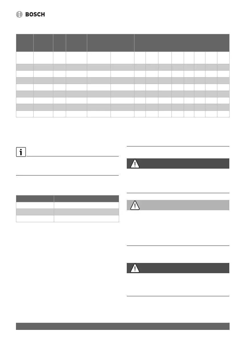
Presents technical data, including voltage, current, and temperature rise.

Installation

Install Location

Provides guidance on selecting the appropriate location for installing the water heater.

Freeze Prevention

Instructions on how to prevent freeze damage to the water heater.

Water Connections

Details the requirements and procedures for connecting the unit to the water supply.

Water Quality

Explains how water quality affects appliance longevity and lists acceptable parameters.

Electrical Connections

Provides instructions and specifications for connecting the unit to the electrical power supply.

Securing the Unit to the Wall

Instructions on how to properly mount and secure the water heater unit to a wall.

Start Up and Operation

Adjusting Flow and Regulating Temperature

How to adjust water flow and regulate the output temperature of the hot water.

Reset Thermal Cut-out

Procedure for resetting the thermal cut-out feature if it is activated.

Troubleshooting

Possible Faults

Lists common problems, their causes, and recommended solutions for the unit.

Electrical Diagram

Provides the internal wiring schematic for the water heater unit.

Interior Components and Parts List

Related product manuals