Key (accessories)
Worcester 2000 – 6 721 814 552 (2019/09)
10
5 Key (accessories)
5.1 Key LED
Key accessory location
▶ The Key can be located underneath the appliance on the right hand
side.
Key LED status
The LED [1] on the Key displays different states with flashing or constant
colours.
Table 4 LED status
For more information please refer to your control manual.
6 Shutdown
6.1 Setting frost protection
NOTICE:
Risk of damage to the system from frost!
The heating system can freeze up after a prolonged period (e.g. during a
power failure, switching off the power supply, faulty fuel supply, boiler
fault etc.).
▶ Ensure that the heating system is in constant use (particularly when
there is a risk of frost).
If you are leaving your property unoccupied during cold weather, please
leave your external programmer on constant and your room thermostat
set to 12 °C.
7 Clearances and ventilation information
7.1 Appliance clearances
Your installer will have provided adequate space around the appliance
for operation, safety and servicing/maintenance access.
• The following detail the necessary clearance around the appliance for
service and maintenance.
CAUTION:
Risk of damage to appliance or property
The appliance will overheat if the clearance space around the appliance
is restricted by objects.
▶ Do not restrict this space with the addition of cupboards, shelves etc.
next to or around the appliance.
▶ Do not store any combustible materials on or next to the appliance,
such as clothes, towels, paper or plastic bags.
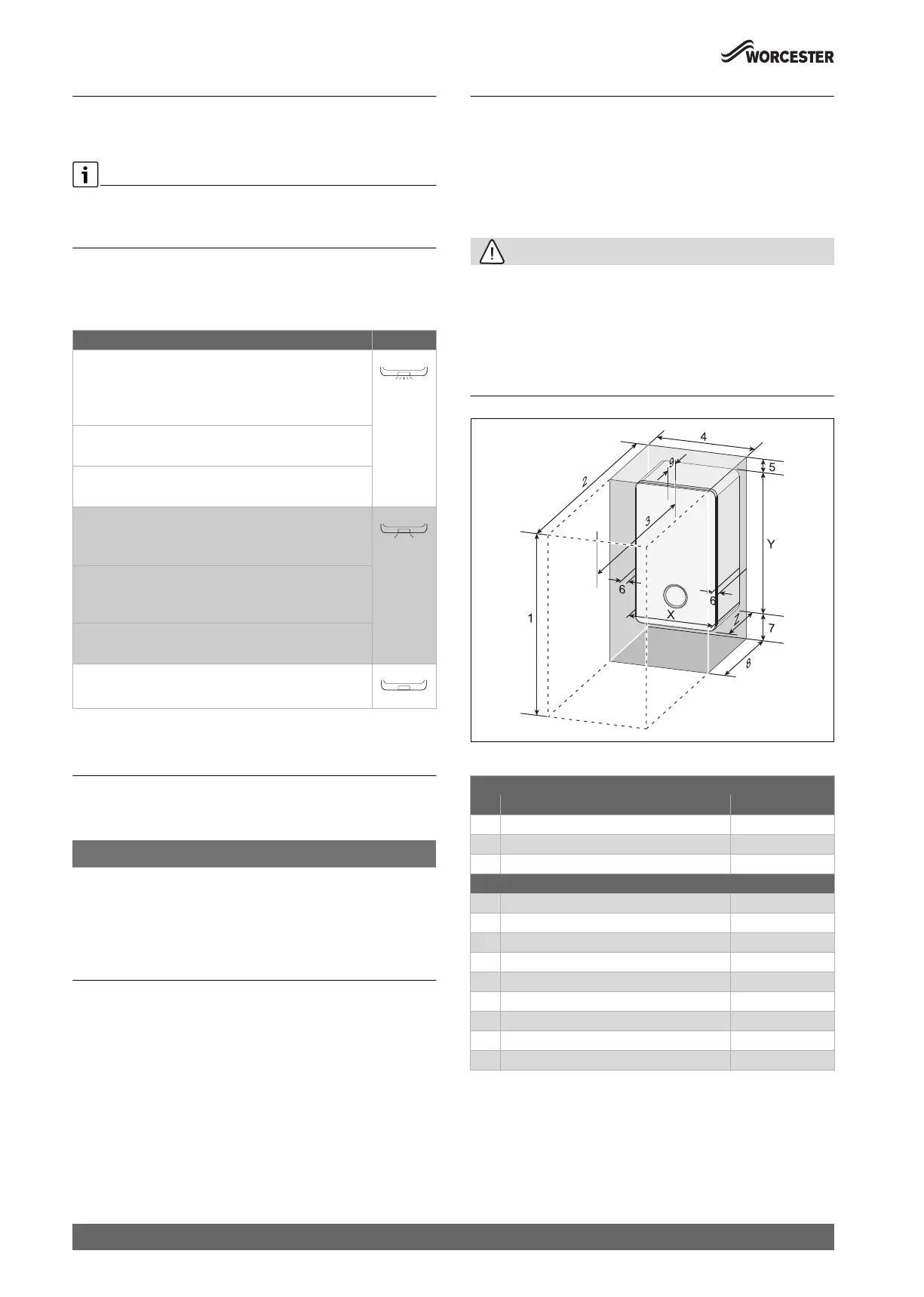
Fig. 7 Appliance minimum clearances
Table 5 Appliance minimum clearances
Description of the LED displays Example
Flashing red:
Fault, e.g. no communication between the Key and
appliance:
▶ Install the key again, restore the last functioning status.
Flashing yellow:
No fault, user please wait.
Flashing green:
No fault, initialisation process is running.
Constant red:
Temporary fault:
▶ Wait for normal operating condition to be resumed.
Constant yellow:
▶ Keys with touch-sensitive indicator: Press touch-
sensitive indicator on key to start pairing.
Constant green:
No fault, normal operating condition.
LED Off:
No fault, power-saving mode or appliance without power.
Minimum clearances
Description Dimensions (mm)
X Appliance width 400
Y Appliance height 724
Z Appliance depth 300
Maintenance
1 Overall clearance height 1115/1155
1)
1) Height for either 60/100 flue or 80/125 flue
2 Overall clearance depth 900
3 In front of appliance 600
4 Overall clearance width 410
5 Above the appliance 191/231
1)
6 Either side of appliance 5
7 Below the appliance 200
8 Compartment depth 320
2)
2) Clearnace to a combustible material
9 Appliance to removable door 20
2)
0010012940-001
 Loading...