2 |
Greenstar6 720 646 558 (2013/07)
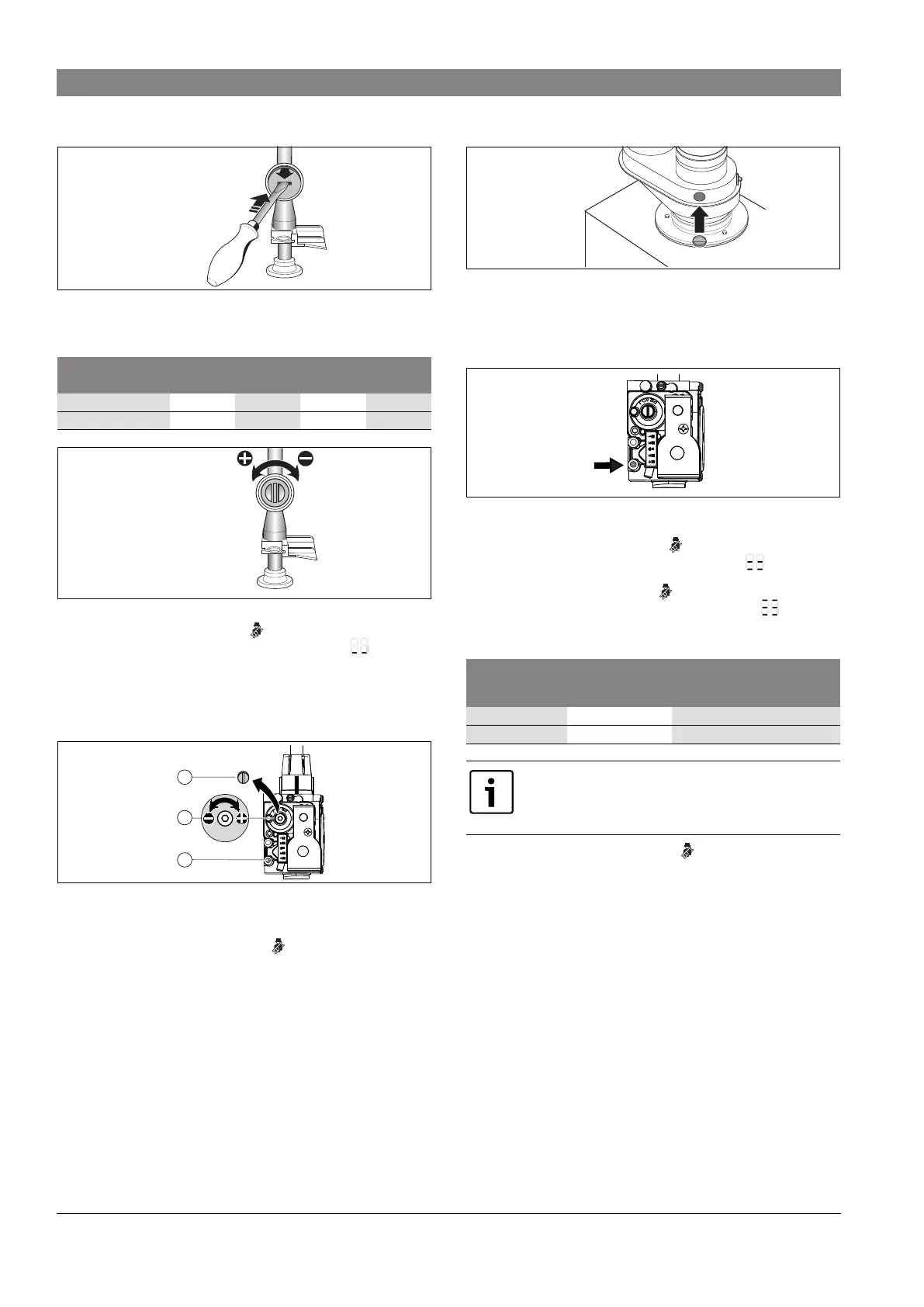
▶ On the the gas throttle break the seal at the slot and remove the cap.
Fig. 4 Remove seal from the gas throttle
▶ Adjust the gas throttle to match the CO
2
or O
2
level for maximum nominal output
according to the following table:
Fig. 5 Set CO
2
or O
2
level for maximum nominal output
▶ Briefly press the emissions test button .
The display shows the supply temperature in alternation with = minimum
nominal output.
▶ Measure the CO
2
or O
2
level and the CO content of the flue gas ( “Installation
and Service Instructions for Contractors”)
▶ Remove the sealed screw ( Fig. 6, [3]) from gas valve adjustment screw
( Fig. 6, [2]) and set CO
2
or O
2
level for minimum nominal output.
Fig. 6 Set CO
2
or O
2
level for minimum nominal output
▶ Re-check settings at maximum and minimum nominal output and re-adjust if
necessary.
▶ Repeatedly press the emissions test button until the light goes out.
The display returns to the supply temperature.
▶ Record the CO
2
or O
2
levels and the CO content of the flue gas in the
commissioning log.
▶ Reinstall the screw ( Fig. 6, [3]) to cover the gas valve adjustment screw.
▶ Remove flue gas probe and close the flue gas test port properly.
Fig. 7 Close flue gas test ports
Dynamic gas pressure test
▶ Switch the appliance OFF and close the gas shut-off valve.
▶ Loosen the screw in the test port for gas inlet pressure
( Fig. 6, [1]) and connect a pressure gauge ( Fig. 8).
Fig. 8 Dynamic gas pressure test port
▶ Turn on the gas cock and switch the appliance ON.
▶ Press and hold the emissions test button until it lights up.
The display shows the supply temperature alternating with = maximum set
output in heating mode.
▶ Briefly press the emissions test button .
The display shows the supply temperature in alternation with = maximum
nominal output.
▶ Check the required gas inlet pressure according to the following table:
▶ Repeatedly press the emissions test button until the light goes out.
The display returns to the supply temperature.
▶ Switch the appliance OFF, turn off the gas cock, remove the pressure gauge and
tighten the screw in the test port for gas inlet pressure.
▶ Reinstall the cover.
Maximum nominal output Minimum nominal output
Gas type CO
2
O
2
CO
2
O
2
NG 9.4 % 4.0 % 8.6 % 5.5 %
LPG (propane) 11.0 % 4.2 % 10.4% 5.1 %
1 .
2 .
6 7 2 0 6 1 2 6 5 9 - 3 7 . 1 R
6 7 2 0 6 1 2 6 5 9 - 3 8 . 1 R
6 720 641 933-81.1O
1
3
2
Gas type
Nominal pressure
" W.C. (mbar)
Permissible pressure range for
maximum nominal output
" W.C. (mbar)
NG 7 (17.4) 3.5-10.5 (8.7-26.1)
LPG (propane) 11 (27.4) 8-13 (19.9-32.3)
Do not operate the appliance if the measured value is below or
above these values. Determine the cause and eliminate the fault. If
this is not possible, block the appliance on the gas side and notify
the gas supplier.
6 720 641 933-80.1O
6 720 614 090-34.2O
 Loading...