21
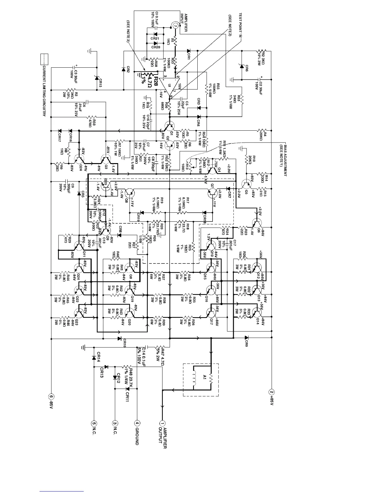
Notes:
1. See Bias Adjustment Procedure.
2. U1 input (pin 2) virtual ground, output test point 8 (pin 6) 275mV.
3. Early production units replace R28 with capacitor C15 (0.1uF) found
in either side of the pc board.
4. All resistors are 1/2 watt 5% unless otherwise specified.
5. All capacitor in uF unless otherwise specified.
Figure 12. Amplifier Schematic Diagram
 Loading...