 Loading...
Do you have a question about the Bose 301 and is the answer not in the manual?
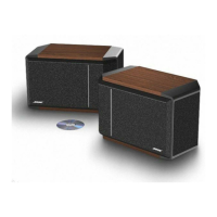
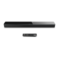
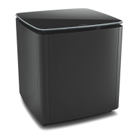
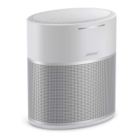
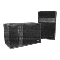
| Type | Bookshelf |
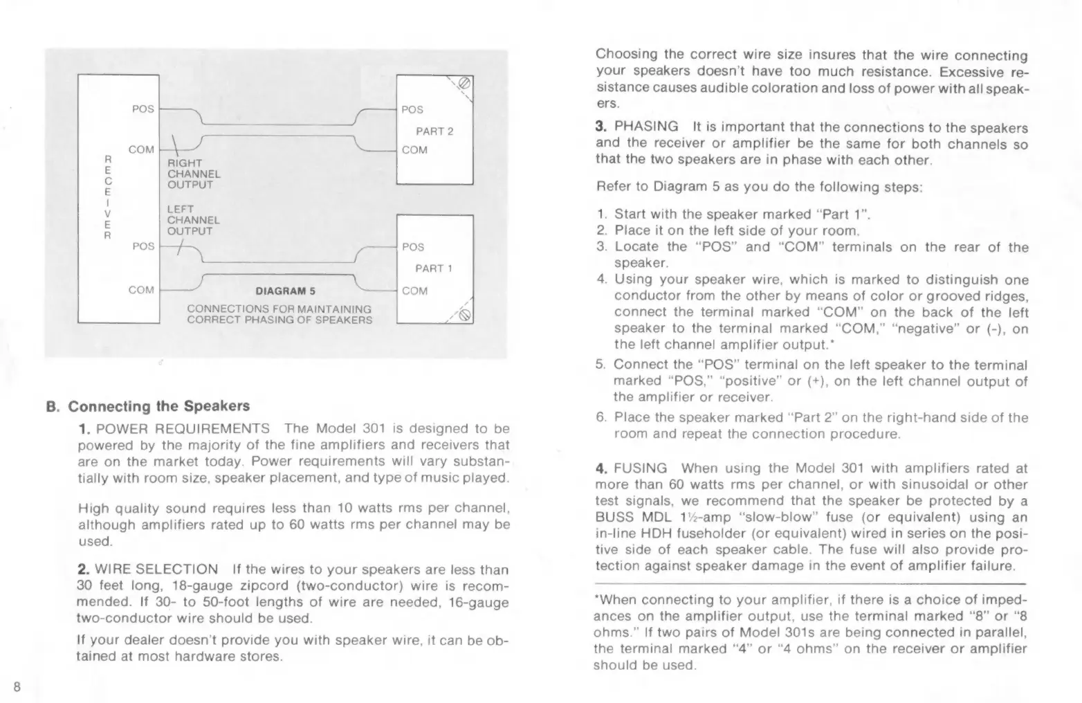
|---|---|
| Equalizer | - |
| Dimensions (WxDxH) | 360 x 250 x 250 mm |
| Tweeter | Yes |
| Speaker placement | Ceiling-mountable |
| Audio output channels | 2.0 channels |
| Impedance | - Ω |
| Frequency range | - Hz |
| RMS rated power | - W |
| Product color | Black |
| Recommended usage | Universal |
| Package weight | 13000 g |
| Connectivity technology | Wired |
| Weight | 5700 g |
|---|