5
3.4 Cut the wires as close as possible to the
driver’s wire terminal.
4. Driver Replacement
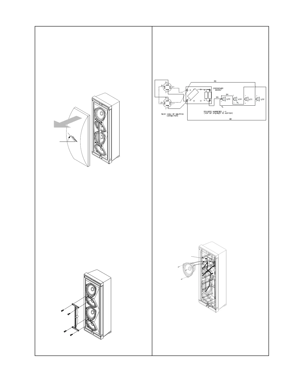
4.1 Referring to the schematic below, attach
the wires to the driver (1).
4.2 Line up the driver (1) to the cabinet and
secure it with three screws (7).
4.3 Line up the deflector (8) with the cabinet
and secure it with four screws (12).
5. Crossover Removal
5.1 Remove the three screws (7) securing the
top driver (1) to the cabinet. Lift out the driver.
5.2 Remove the two screws (7) securing the
crossover PCB to the cabinet.
5.3 Pull the crossover PCB through the driver
opening in the cabinet.
Deflector
Crossover PCB
DISASSEMBLY/ASSEMBLY PROCEDURES
45
0
Note: Numbers in parenthesis correspond to
call-outs in figure 1.
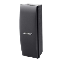
1. Grille Removal
1.1 Rotate the Bose
®
logo (9) 45
0
to release
the grille (6).
1.2 Grasp the edge of the grill and pull it off.
2. Grille Replacement
2.1 Rotate the Bose logo (9) 45
0
so the
locking tabs on the logo line up with the slot
on the deflector (8). Press the grille into place.
2.2 Rotate the Bose logo horizontally, locking
the grille into place.
3. Driver Removal
3.1 Perform procedure 1.
3.2 Remove the four screws (12) securing the
deflector (8) to the cabinet. Lift off the deflector.
3.3 Remove the three screws (7) securing the
driver (1) to the cabinet. Lift out the driver.
 Loading...