Product Overview
ESP-880AD
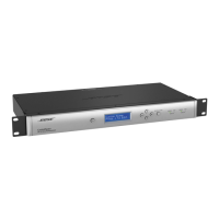
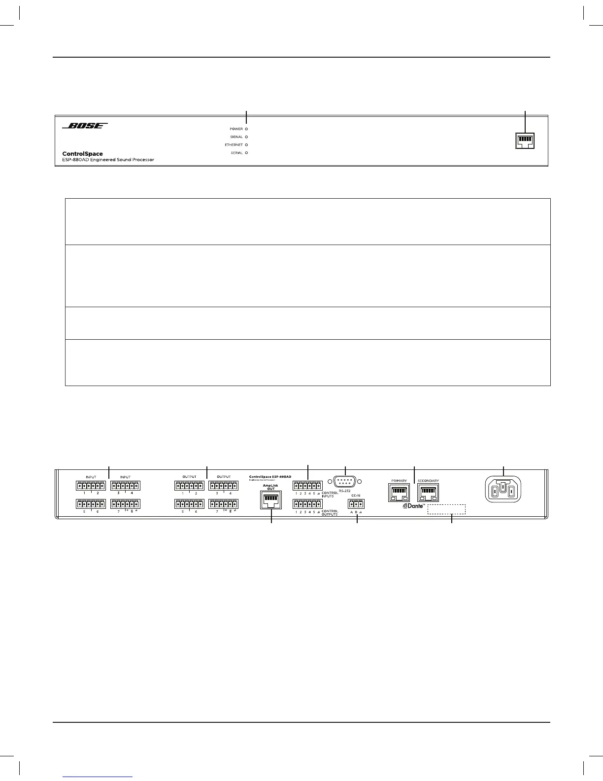
Front Panel
q LED Indicators:
Power: Power or fault state indication. Green: Power on, normal operation
Yellow: Powering on
Red: Error (see Troubleshooting on page 22)
Signal: Signal status indication of all audio input
and output channels in order of signaling
priority. For precise metering and gain
control, connect using ControlSpace
Designer software.
Green: Signal present (–60 dBFS to –20 dBFS)
Yellow: Signal level optimal (–20 dBFS to –2 dBFS)
Red: Clipping (–2 dBFS to 0 dBFS)
Ethernet: Connection status indication of Ethernet
ports.
Green: Ethernet link established
Yellow: Active transmission/reception
Serial: Serial command status indication for
CC-16 zone controller or RS-232 device.
Green: CC-16 controller command transmitted
Yellow: CC-16 controller command received
Red: Active RS-232 transmission/reception
w Ethernet port: RJ-45 port for front-panel network connectivity. See 8. Connecting to a Network (page 21)
for more information.
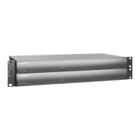
Rear Panel
q Audio Inputs & Outputs: Mic-/line-level inputs and line-level outputs balanced analog audio signals.
See 4. Connecting Analog Audio Devices (page 18) for more information.
w AmpLink Out port: Ethernet connection for use with AmpLink-equipped PowerMatch amplifiers.
See 5. Connecting ControlCenter, AmpLink & Serial Control Devices (page 19) for more information.
e Serial number.
r RS-232 port: Five-wire, RS-232 (DTE) serial interface connection.
t Power input: Power cord connection (IEC 60320-C14 inlet).
y Dante ports (Primary & Secondary): Ethernet ports for connection of Dante devices. See 6. Connecting
Dante-compatible Devices (page 19) for more information.
u CC-16 connector: RS-485 network connection for up to 15 CC-16 zone controllers.
See 5. Connecting ControlCenter, AmpLink & Serial Control Devices (page 19) for more information.
i Control Inputs & Outputs: Five inputs and five outputs for general-purpose control. See 7. Connecting
GPIO Devices (page 20) for more information.
q w
i r
uw
y
e
t
q q

 Loading...