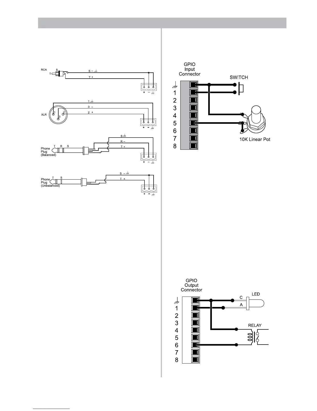
Audio connections
A microphone or line level audio source can be con-
nectedtotheMic/Lineinputsusingoneofthefollowing
wiring methods.
General Purpose Inputs/Outputs (GPIO)
cards
TwoGPIOcardslotsprovideupto16controlinputs
and16controloutputs.TheGPIOinputsareusedto
accept hardware-based control signals from switches,
relays or potentiometers.
Inputs
Switches and potentiometers can be connected to
the control inputs to control various functions in the
system.Forexample,simpleON/OFFswitchescanbe
connected and then programmed to invoke presets,
select scenes, or invoke a snapshot of a control. Like-
wise, 10k potentiometers (linear) can be connected to
control gains in the system.
When used for gain control, the control input expects
tosee0ohmsforfullgainand10kohmsfor"OFF"or
muted. This is to prevent unterminated or loose con-
nections from inadvertantly causing full-gain audio,
since the port features an internal pull-up resistor.
Therefore, wire the potentiometer such that the fully
rotated clockwise position (full gain from the user's
perpective) is 0 ohms and the fully counterclockwise
position is 10k ohms.
Outputs
LEDs and relays can be connected to general purpose
outputs to indicate state changes in the system (e.g.
preset or scene changes).
Amaximumof10mA(sink;0.5mAsource)peroutput
is available and therefore care must be taken when
selecting components. Select LEDs that are “High
Efficiency” and require only 10mA forward current. For
relays, only those rated with an LED forward current
of 10mA or less, such as some solid state relays, can
be connected directly. Most mechanical relays require
more than 10mA drive current and are not suitable for
direct connection. Alternatively, an external power sup-
ply and transistors can be used to drive higher current
LEDs or relays.
Modularity and Expansion
Inputs include a 5k ohm pull-up resistor allowing SPST
switches to be wired from input to ground. Potentiom-
eters can be wired in series from the control input to
ground.
 Loading...