10
TEST PROCEDURES
1. Air Leak Test
1.1 Remove the right-hand grille cap to gain
access to the tap rotary switch. Set the
switch to the 8 Ohm setting.
1.2 Apply a 7 Vrms, 95 Hz signal to the input
terminals of the loudspeaker.
1.3 Listen for any air leaks around the driver,
the rubber grommet located on the back of
the speaker and any seams. Reject any
speaker with an air leak. All repairs must be
hidden. Replace any driver that has a rubbing
or ticking noise.
2. Rub and Tick Test
2.1 Remove the right-hand grille cap to gain
access to the tap rotary switch. Set the
switch to the 8 Ohm setting.
2.2 Apply a 7 Vrms, 95 Hz signal to the input
terminals of the loudspeaker.
2.3 At a distance of less than one foot, listen
for any extraneous sounds from the speaker.
Replace any driver that has a rubbing or
ticking noise.
Note: There is a normal suspension noise.
To distinguish between a rub or tick or
suspension noise, displace the cone slightly
with your finger. If the rubbing can be made
to go away or get worse, then it is a rub or a
tick. If the noise stays the same, it is a
suspension noise.
3. Power Sweep Test
3.1 Remove the right-hand grille cap to gain
access to the tap rotary switch. Set the
switch to the 8 Ohm setting.
3.2 Apply a 7 Vrms, 50 Hz signal to the input
terminals of the loudspeaker.
3.3 Change the oscillator frequency slowly
from 50 Hz to 5 kHz. Listen for any buzzes,
rattles or other extraneous noises from the
driver or from the internal parts. The
whooshing noise from the port at around
95 Hz is acceptable.
Replace any driver that has a buzzing noise.
Ensure that there are no buzzes or rattles
from any internal parts.
4. Transformer Tap Select Test
4.1 Remove the right-hand grille cap to gain
access to the tap rotary switch. Set the
switch to the 70V, 16W setting.
4.2 Apply a 70 Vrms, 100 Hz signal to the
transformer input (70V/100V) of the loud-
speaker.
4.3 Slowly change the tap selection from the
high position (16W) to the 2W position. A
decrease in level should be heard for each
descending tap.
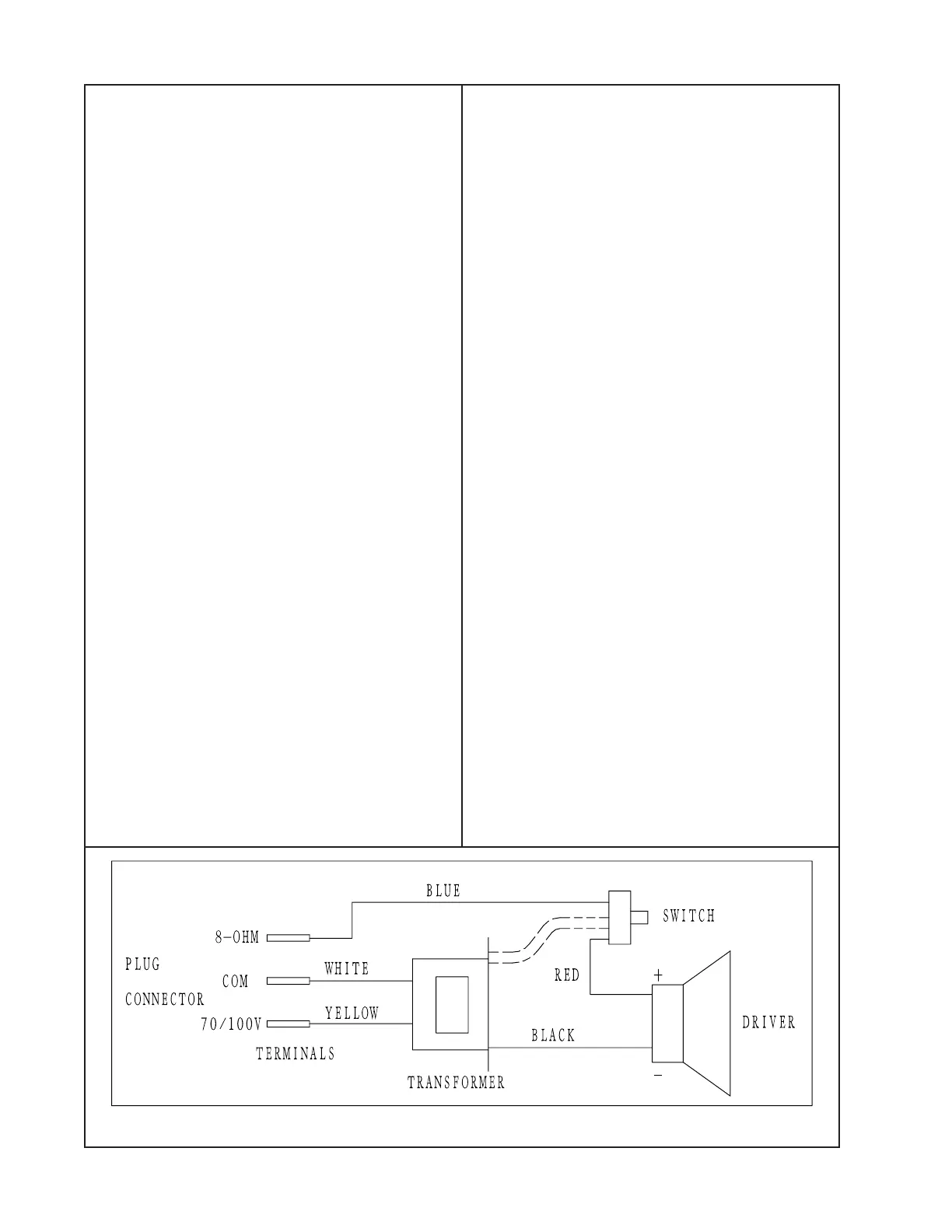
Figure 5. Loudspeaker Wiring Diagram
 Loading...