33
TEST PROCEDURE
Required Equipment:
1. Bose L1 Pro32 Power Stand, Line Array and Sub1/Sub2 bass module (UUT)
2. Audio Signal Generator, Audio Precision ATS-1 or equivalent
3. Multimeter
4. Cables listed below:
- XLR audio cable
- 1/4 inch TRS audio cable
- Bose SubMatch cable (bass module connection)
- AC Line cords - per region - refer to packaging part list
Set-up & Connections:
- Connect the Sub1/Sub2 bass module to the
power stand using the SubMatch cable
- Connect the Power Stand AC line cord to
AC Mains.
- Assemble the Line Array to the Power Stand
Functional Tests:
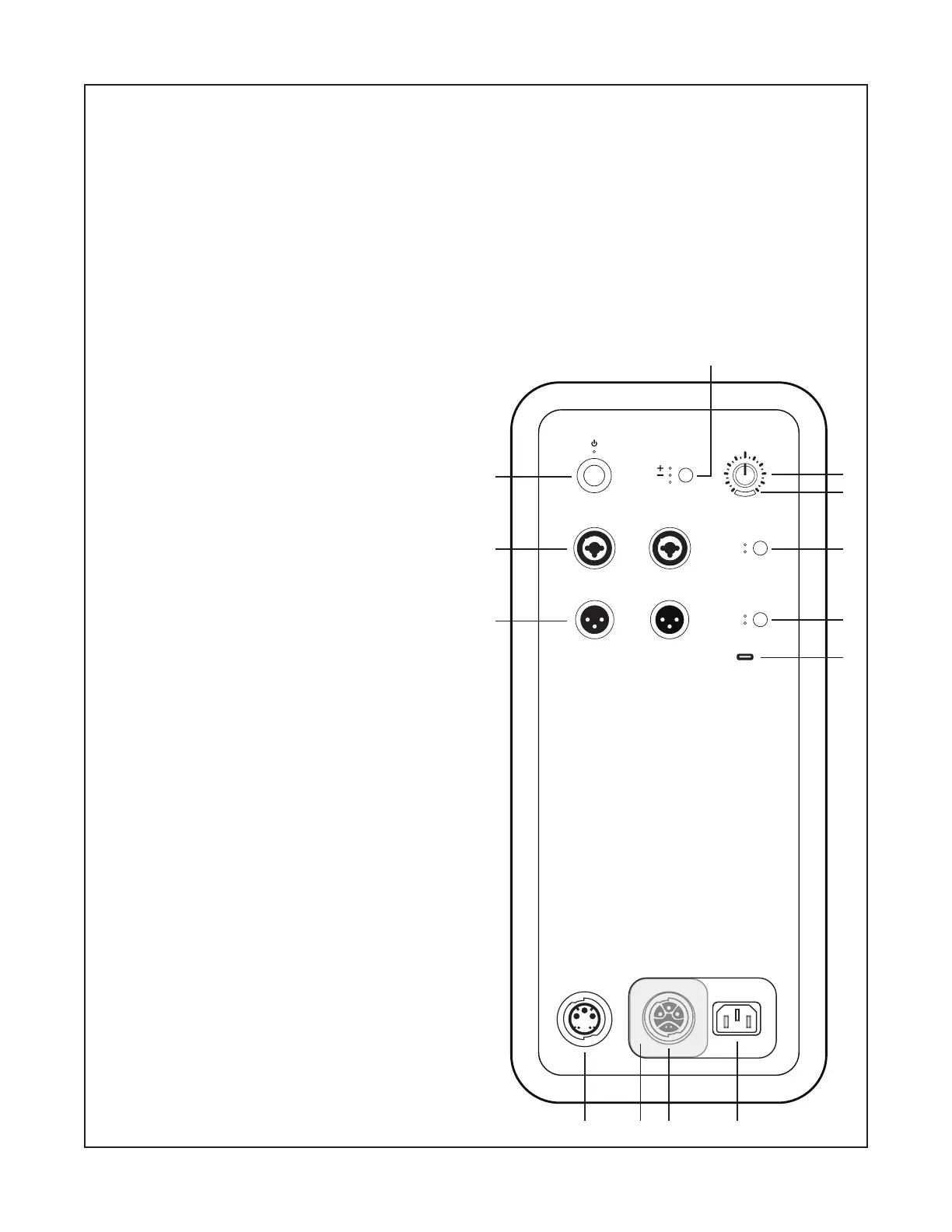
1. Button and Knob Functionality Test
Refer to the Figure at right for this test
1.1 Press the STANDBY button (1) on the Power
Stand to turn on the power stand. Verify that the
LED lights.
1.2 Rotate the Level Control knob (12).
Note: The Signal/Clip LED (11) will be tested
during the signal input tests later in this procedure.
1.3 Press the Phase/Pattern button (13) to step
through each of the selections. Verify that the
associated +, - and Cardioid LEDs light correctly.
Note: You must press and HOLD the Phase/
Pattern button for 4 seconds in order for the
Cardioid LED to light.
1.4 Press the Line Input EQ button (10). Verify
that the LPF/L1 LEDs light correctly as you step
through the selections.
1.5 Press the Line Output EQ button (9). Verify
that the FULL/HPF LEDs light correctly as you step
through the selections.
LINE IN 1LINE IN 2 LINE IN EQ
LINE OUT 1LINE OUT 2LINE OUT EQ
PHASE/PATTERN
LEVEL
LPF
L1
FULL
HPF
SUBMATC H
THRU
SUBMATC H
IN
CARDIOID
9
8
 Loading...