16
G
ETTING YOUR HEADSET READY FOR USE
Details on making the connections
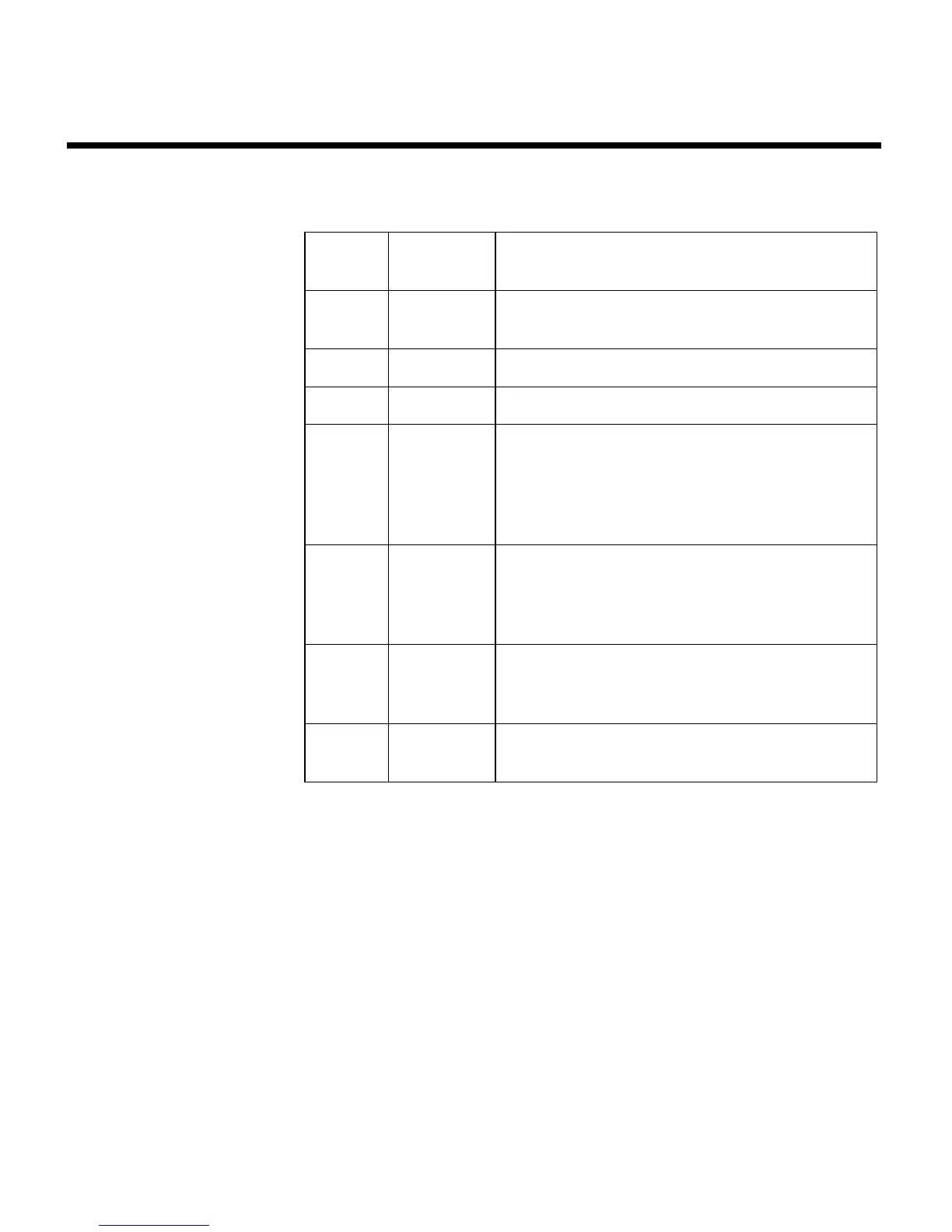
The pinout for the optional installed connector is:
1 Red Headset power (10-32 VDC). Use a
1
/
4
-amp
fuse or a
1
/
2
-amp circuit breaker.
2 Black System ground. Connect to the existing
audio ground.
3 White Phone communication–Left.
4 Black Phone communication–Right.
5 White Microphone/Hi-audio. Connect to the por-
tion of the existing microphone jack that
corresponds to the ring position of a head
-
set microphone plug. Do not connect to
the tip (PTT) segment.
6 White/
Blue
Microphone/Lo-ground. Connect to the
portion of the microphone jack that corre
-
sponds to the barrel position of a headset
microphone plug.
Comm
Shield
Black Shield from Comm L and Comm R wire
pair.
Mic
Shield
Black Shield from Mic Hi and Mic Lo wire pair.
 Loading...