Store this
booklet for
future reference
© 2004 Braeburn Systems LLC • Patents Pending • All Rights Reserved. Pub. No. 1200-100-006
Braeburn Systems LLC warrants each new Braeburn thermostat against any defects that are
due to faulty material or workmanship for a period of five years after the original date of
purchase by a professional service technician. This warranty and our liability does not apply to
batteries, nor does it include damage to merchandise or the thermostat resulting from
accident, alteration, neglect, misuse, improper installation or any other failure to follow
Braeburn installation and operating instructions.
Braeburn Systems LLC agrees to repair or replace at its option any Braeburn thermostat
under warranty provided it is returned postage prepaid to our warranty facility in a padded
carton within the warranty period, with proof of the original date of purchase and a brief
description of the malfunction. This limited warranty does not include the cost of removal or
re-installation.
This warranty gives you specific legal rights and you may also have other rights that vary from
state to state or province to province. Answers to any questions regarding our limited warranty
may be obtained by writing our corporate offices.
WARRANTY FACILITY: Braeburn Systems LLC
Attn: Warranty Department
2215 Cornell Avenue
Montgomery, IL 60538
Braeburn Systems LLC
2215 Cornell Avenue • Montgomery, IL 60538
Technical Assistance: www.braeburnonline.com
Call us toll-free: 866-268-5599 (U.S. Only)
630-844-1968 (Outside the U.S.)
8
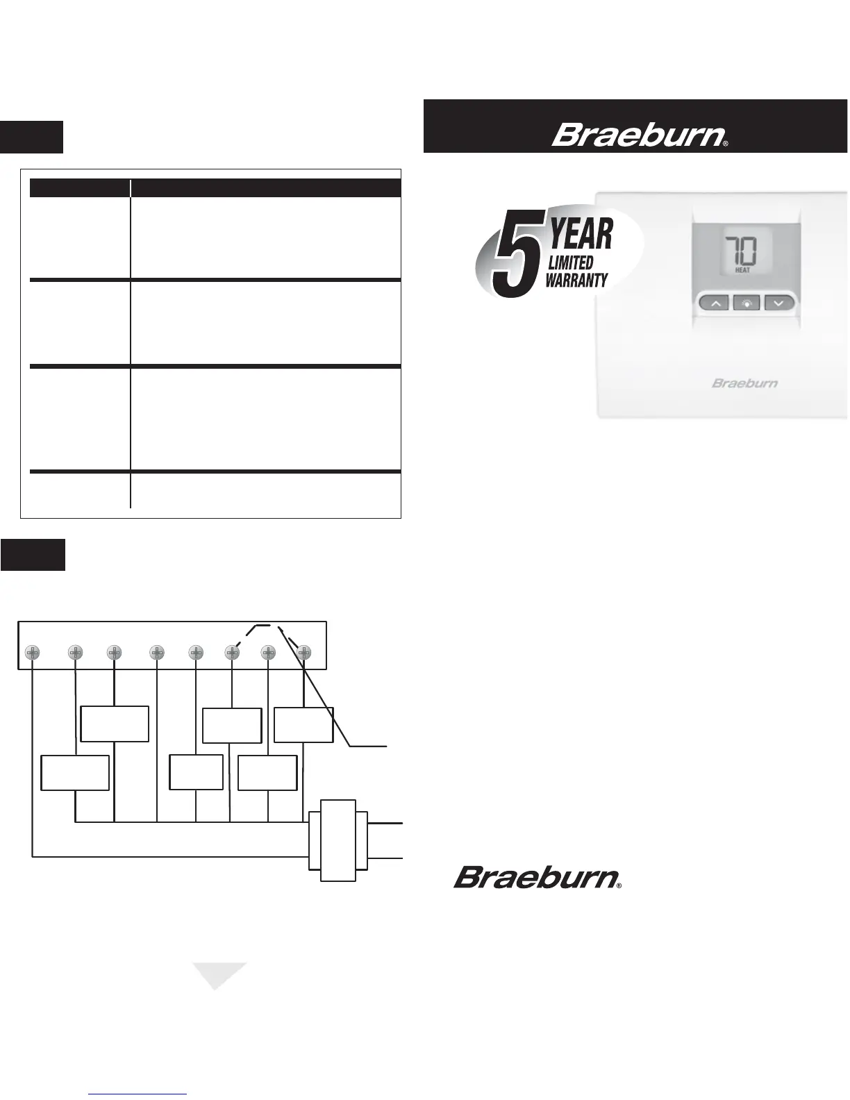
WIRING DIAGRAM
7
Thermostat will not
allow me to program
a setpoint
temperature higher
than 90˚ F (32˚ C).
This is above the normal thermostat temperature setting range
of 45˚ to 90˚ F (7˚ to 32˚ C).
Thermostat will not
allow me to program
a setpoint
temperature lower
than 45˚ F (7˚ C).
This is below the normal thermostat temperature setting range
of 45˚ to 90˚ F (7˚ to 32˚ C).
Fan continues to run
all the time whether
the system is on
or off.
Check that the fan control switch is in the AUTO position. This
will allow the fan to run only when the heating or cooling system
is turned on and running.
Check thermostat wiring to make sure that the fan control
wiring is connected to the correct terminals on the wiring
terminal block. See Installation and Wiring Diagram sections of
this manual.
The room is too
warm or too cold.
See Review Set Temperature section of this manual to verify the
current setpoint and make any modifications that are necessary.
SYMPTOM POTENTIAL SOLUTION
TROUBLESHOOTING
6
cont.
R O
Changeover
Relay - Cool
B Y
G W2
Transformer Common
(Required)
Compressor
Contact
Emergency
Heat Relay
Auxiliary Heat
Relay (Stage 2)
Fan Relay
24 VAC
Hot
120 VAC
Neutral
See Note 1
Wiring Diagram for 2 Stage Heat, 1 Stage Cool
NOTE: 1. Jumper is required to use Auxiliary Heat for both Second Stage and
Emergency Heat on units without separate Emergency Heat and Auxiliary
Heat terminals.
2. Make O / B connections as required by unit.
Changeover
Relay - Heat
C E

 Loading...