Page 5Supplement 29376
Series A6 and Installation Supplement 29376
Series A6 & Installation Supplement 29376
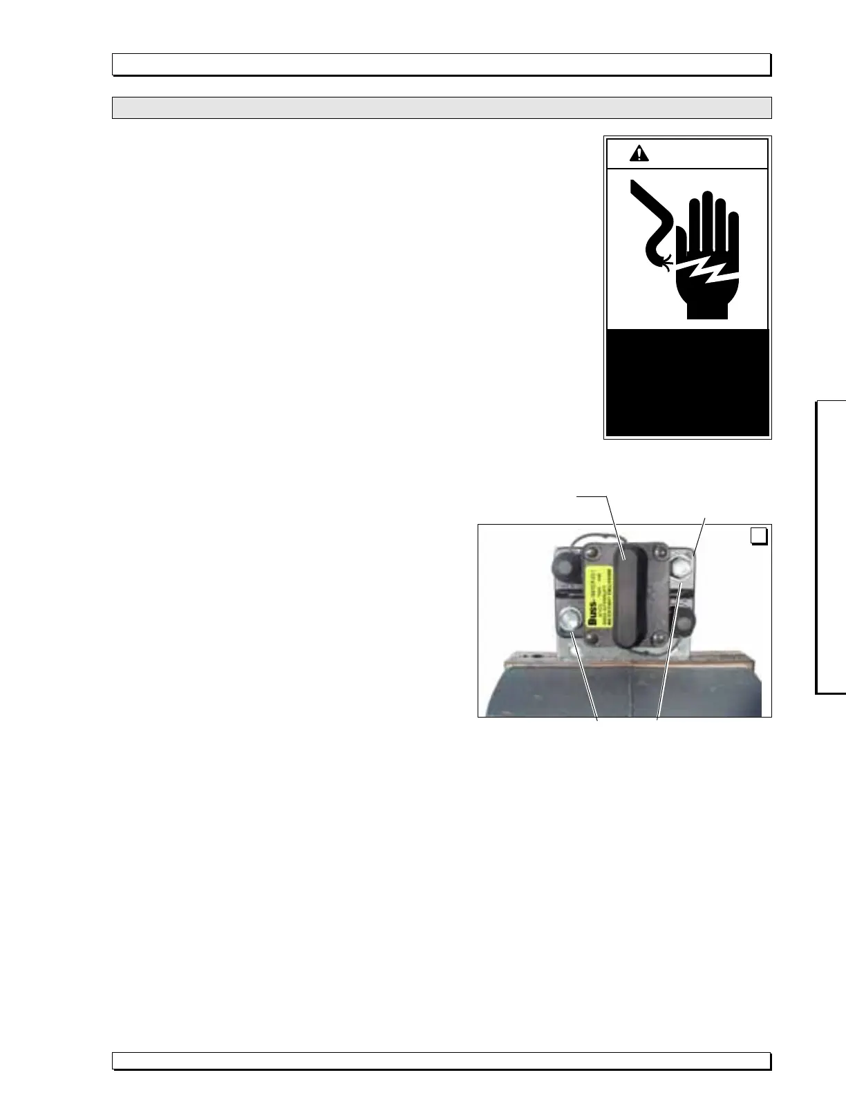
1/4-14 x 1" Washer Hex Head Self-Drilling Screws
Flush Mount
Bracket 28755
100 Amp. Circuit
Breaker 28704
A
Circuit Sentry Kit 28910KS is
supplied to provide greater
installation versatility (less space
required). Two types of mount-
ing brackets are supplied (shown
in Figure 2). Bracket 28755 is a
flush mount bracket (without
offset). Bracket 28498 is an
offset mount bracket. Either
bracket can be used as desired.
Select an appropriate mounting
surface in the engine compart-
ment or vehicle battery location.
Select the appropriate mounting
bracket based on the available
mounting surface and other
variables. Mounting brackets can
be oriented as needed.
The Circuit Sentry must be
positioned such that the lead
cable will reach the vehicle
battery. Locate the Circuit Sentry
within 24" of the positive (+)
battery terminal.
Note: Photos of the compact
Circuit Sentry installed in Dodge
and Ford vans appear in Service
Bulletin 28911 (supplied with
each Compact Circuit Sentry Kit).
Mount Circuit Breaker
Mount the circuit breaker to the
mounting bracket. See Figure B
and Photo A. Four .191" diameter
holes spaced 1" apart are pro-
vided in each mounting bracket.
The holes match the pattern of
circuit breaker mounting holes.
Place the bracket securely in a
vice gripping the edge that does
not obstruct positioning of the
circuit breaker (see Photo A).
Mount the breaker to the bracket
using two 1/4-14 x 1" washer hex
head self-drilling screws.
#8-18 x 3/4" wafer head self-
drilling screws are supplied to
mount the circuit breaker and
mounting bracket assembly.
Note: Optional (OEM) mounting
hardware can be utilized in some
applications. Mount the bracket
as needed.
Check for obstructions such as
fuel lines, coolant lines, wires,
exhaust, etc. before drilling.
Cable Connections
Remove the rubber caps
attached to the circuit breaker
terminals. Attach the lift power
cable to the Auxiliary terminal
of the Circuit Sentry. Attach one
end of the battery lead cable to
the Circuit Sentry Battery
terminal. Tighten securely.
Reposition the rubber caps onto
the breaker terminals to prevent
electrical short circuits. Care-
fully connect the opposite end
of the battery lead cable to the
Positive (+) post of the battery.
Decal 18181
Post decal 18181 adjacent to
the Circuit Sentry assembly
(provides circuit breaker reset
instructions).
Note: Clean the surface with
isopropyl alcohol before decal
application. Use a clean cloth
or paper towels. DO NOT use
oily shop rags. Wipe surface
free of residue with dry portion
of cleaning cloth.
Compact Circuit Sentry
Circuit Sentry Installation and Power Connection (reference page 19)
W
A
RNING
Risk of electrical
shock! Use extra
care when making
electrical connec-
tions.
 Loading...