EasyManua.ls Logo

Braun L917FIB User Manual

Braun L917FIB
95 pages
To Next Page IconTo Next Page
To Previous Page IconTo Previous Page
Page #81 background image
Output Type: Negative Film/Right Reading/Emulsion side DOWN
Page(s): Date:
Document:
Cut 11" x 17" sheet vertically here
(15/16" from edge)
Cut 11" x 17" sheet vertically here
(15/16" from edge)
Fold trimmed sheet here (7-9/16" from edge)
Color Separation:
137
138
138
137
38
41
126
122
122
123
38
127
128
125
41
128
127
126
38
41
122
125
122
128
128
124
38
41
59
22
64
59
22
64
67
21
69
67
21
68
77
60
60
63
65
66
60
65
60
58
64
66
61
62
1
34
47
48
51
55
133
56
47
47
110
19
70
64
64
57
49
53
15
48
48
48
47
47
47
23
17
35
35
52
47
47
73
72
47
48
48
51
47
47
53
133
56
112
12
112
36
112
11
27
24
111
111
14
120
113
13
10
111
112
64
74
92
90
91
91
89
93
85
85
82
82
103
99
105
104
96
68
68
80
110
121
20
3
2
33
79
112
70
64
60
60
65
66
66
60
65
60
49
57
16
48
48
47
47
47
23
18
64
61
62
13
52
52
47
47
75
99
98
102
98
102
101
94
95
97
86
86
81
6
89
99
4
98
L916 / L917 Only
121
63
83
84
84
5
106
116
116
106
107
107
7
8
108
100
109
28
26
27
28
26
27
27
26
25
76
76
112
27
27
27
27
79
79
112
71
78
112
112
58
117
118
119
118
81
33
27
26
25
31
29
30
30
79
13
112
112
112
78
39
39
40
78
115
116
40
39
40
39
40
39
40
39
40
38
41
38
41
39
40
39
40
38
41
38
41
112
27
114
80
37
37
80
68
69
8
67
42
43
42
46
44
9
44
43
45
45
69
68
87
88
87
88
86
111
111
111
111
111
111
129
130
131
131
130
129
31
33
29
30
30
32
32
111
111
132
132
50
136
136
136
79
79
79
135
134
34
52
78
54
55
57
54
57
6-0267B & 68B
25522-06/6-02/p.67&68
Page 68BPage 67B
Unfold for:
42" Floor-To-Ground
Fixed Inboard Roll Stop
Non-IB Lift Models
Exploded View
48" Floor-To-Ground Fixed Inboard Roll Stop Non-IB Lift Models Exploded View
Series 06
L916 L916F
L917 L917F
L919 L919F
Note: Illustrations depict components as
equipped when specified lift series was in
production. Replacement components
may reflect newer lift series configurations.
June 2002 Update June 2002 Update
25522-06/6-02/p.67&68 6/4/02, 5:05 PM3

Table of Contents

Question and Answer IconNeed help?

Do you have a question about the Braun L917FIB and is the answer not in the manual?

Braun L917FIB Specifications

General IconGeneral
BrandBraun
ModelL917FIB
CategoryLifting Systems
LanguageEnglish

Summary

Installation Updates and Revisions

Lift Grounding Updates

Describes a specific installation update for grounding.

Compact Circuit Sentry Kit Update

Details an update for the circuit sentry kit.

Installation Parts List Revisions

Refers to parts list updates for installation.

Service Information and Part Modifications

Series A6 Solenoid Technical Details

Technical information specific to Series A6 lifts.

Platform Side Plate Modification Details

Describes a modification to platform side plates.

Installation Parts and Required Tools

Part Number Updates

Lists changes to part numbers for installation.

Additional Installation Parts

Details installation parts not originally listed.

Tools Required for Installation

Lists the tools needed for installation.

Lift Grounding and Cabling Installation

Power and Ground Cable Installation

Guides on installing power and ground cables.

Pump Mounted Ground Cable Routing

Details on routing and securing the pump ground cable.

Vehicle Battery Ground Cable Connection

Instructions for connecting the battery ground cable.

Compact Circuit Sentry Installation

Circuit Sentry Installation and Power Connection

Guides the installation and power connection of the circuit sentry.

Mounting the Circuit Breaker

Details on mounting the circuit breaker.

Circuit Sentry Cable Connections

Instructions for connecting the circuit breaker cables.

Electrical System Diagrams

Series A6 Electrical Schematic

Shows the electrical layout of the Series A6 lift system.

Series A6 Wiring Diagram

Visual representation of the Series A6 lift's electrical connections.

Lift Wiring Diagram

Visual representation of the lift's electrical connections.

18 Guage Control Box Schematics

Diagrams specific to the 18-gauge control box.

Pump Module Diagrams and Parts Lists

Rear Pump Module Parts List

Lists all parts for the rear pump module.

Control Box and Harness Options

Lists available control box and harness configurations.

Rear Pump Module Diagram

Exploded view diagram of the rear pump module components.

Front Pump Module Diagrams and Parts Lists

Front Pump Module Parts List

Lists all parts for the front pump module.

Control Box and Harness Options

Options for control boxes and harnesses.

Front Pump Module Diagram

Exploded view diagram of the front pump module components.

Lift Repair Parts and Exploded Views

Lift Exploded Views Reference

Refers to detailed diagrams of lift components.

Platform Side Plate Modification Details

Details a modification to the platform side plate.

42" IB Lift Repair Parts and Views

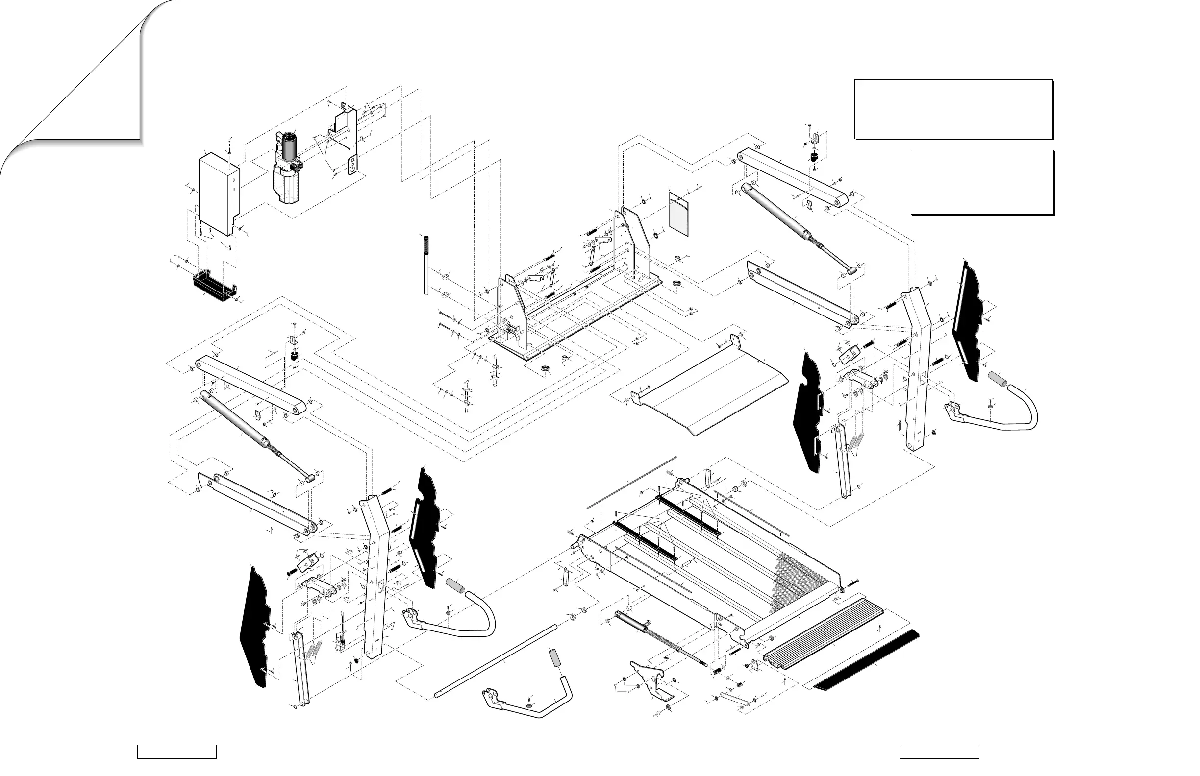
Lists repair parts and provides exploded views for 42" IB lift models.

48" IB Lift Repair Parts and Views

Lists repair parts and provides exploded views for 48" IB lift models.

Lift Terminology and Component Definitions

Introduction to Lift Terminology

Overview of the L915 Millennium Series lifts.

Direction Definitions

Defines terms like "left (rear)" and "right (front)".

Major Lift Components Explained

Describes key parts including pump module, frame, platform, and roll stops.

Installation and Service Safety Precautions

Safety Symbols Explained

Explains warning and caution symbols used in the manual.

General Safety Warnings

Outlines critical safety warnings for installation and service.

Operational Safety Guidelines

Rules for safe operation and maintenance.

Personnel and Parts Safety Guidelines

Guidelines on authorized personnel and replacement parts.

Pre-Installation Procedures and Checks

Installation Requirements and Vehicle Preparation

Specifies personnel, door opening, and vehicle preparation needs.

Chassis Grounding and Wiring Procedures

Details grounding requirements and related wiring.

Installation and Maintenance Checklists

Mentions the lift installation and preventive maintenance checklists.

Lift Installation Procedures

Installation Parts and Tools Required

Lists all required installation parts and tools.

Lift Securement Procedures

Details on securing the lift's base plate and using reinforcement brackets.

Power Cable and Ground Cable Installation

Instructions for installing power and ground cables.

Circuit Sentry Installation and Power Connection

Guides the installation and power connection of the circuit sentry.

Control Box and Harness Installation

Harness Types and Connection

Describes harness types and the connection procedure.

Control Box Mounting and Harness Routing

Guidelines for mounting the control box and routing the harness.

Post-Installation Testing and Adjustments

Test Lift Operation Procedure

Steps to test lift operation after installation.

Positioning and Clearance Checklist

Verification of lift placement and clearances.

Platform Angle and Floor Level Adjustment

Guides for adjusting platform angle and floor level.

Quiet-Ride Adjustment Instructions

Instructions for adjusting components to reduce rattles.

Lubrication and Maintenance Schedule

Lubrication Diagram and Chart

Visual guide and table for lubrication points and products.

Maintenance and Lubrication Schedule

Outlines procedures for scheduled maintenance and lubrication intervals.

Systems Descriptions

General Operation Overview

Explains how the lift operates, including automatic features.

Electrical System Components

Describes the power source, pump motor, relay, and circuit sentry.

Solenoid and Circuit Breaker Functions

Explains the operation of solenoids and the circuit breaker.

Microswitch Functions and Adjustments

Describes microswitches and their adjustment procedures.

Hydraulic System Details

M268 Hydraulic Pump and Fluid

Describes the pump, fluid requirements, and contamination handling.

Hydraulic Valves and Pressure Switch

Explains valves and the pressure switch function and adjustment.

Manual Backup Pump and Cylinder Systems

Covers manual pump operation and cylinder troubleshooting.

Lift Interlock Installation Procedures

Interlock Installation Instructions

Steps for connecting the remote interlock switch.

Interlock System Specifications

Details on wire gauge and distance for interlock switches.

Hydraulic System Schematic

Hydraulic System Diagram

Illustrates the fluid flow and components of the hydraulic system.

Repair Parts Lists and Exploded Views

Rear Pump Hydraulics Parts List

Comprehensive list of hydraulic parts for the rear pump module.

Front Pump Hydraulics Parts List

Lists all parts for the front pump module.

42" IB Lift Exploded Views

Exploded view illustrating components of 42" IB lift models.

48" IB Lift Exploded Views

Exploded view illustrating components of 48" IB lift models.

Non-IB Lift Repair Parts and Exploded Views

42" Non-IB Lift Exploded View

Exploded view of components for 42" Non-IB lift models.

48" Non-IB Lift Exploded View

Exploded view of components for 48" Non-IB lift models.

48" Non-IB Lift Repair Parts List

Lists repair parts for 48" Non-IB lift models.

Decals and Antiskid Application

Decal Application Procedures

Instructions for cleaning and applying decals.

Non Lift-Posted Decals

Lists and shows decals for the control box area.

Antiskid Tape Application

Details on antiskid tape sizes, colors, and part numbers.

Lift-Posted Safety and Operational Decals

Identifies and describes various decals affixed directly to the lift.

Lift Specifications and Performance Data

Model and Weight Specifications

Lists lift models and their corresponding weights.

Key System Specifications Overview

Covers lift series code, pump, fluid, pressure relief, capacity, and power source.

Operations Cycle Times and Specifications

Provides performance data and operational parameters.

Warranty and Registration Procedures

Five-Year Limited Warranty Details

Details the terms and conditions of the lift's warranty.

Return Authorization Procedure Guide

Explains how to process warranty claims and returns.

Lift Dimensions and Clearances

Dimension Descriptions and Definitions

Defines key dimensions used in the specification charts.

Non-IB Lift Model Dimensions

Provides dimensional specifications for fixed inboard roll stop models.

IB Lift Model Dimensions

Provides dimensional specifications for automatic inboard roll stop models.

Daily Preventive Maintenance Schedule

Pre-Trip Inspection Checklist

Items to inspect before daily lift operation.

Post-Trip Inspection Procedures

Procedures to follow after daily lift operation.

Lift Installation Checklist

Positioning and Clearance Checklist

Verification of lift placement and clearances.

Alignment Verification Steps

Checks for proper side-to-side and inboard-to-outboard alignment.

Platform Operation Checks

Verifies clearance during platform movement.

Installation Details Verification

Confirms proper installation of key components and procedures.

Related product manuals