7
Briggs & Stratton Power Products Home Standby Generator
Installation, Start-Up and Owner’s Manual
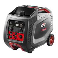
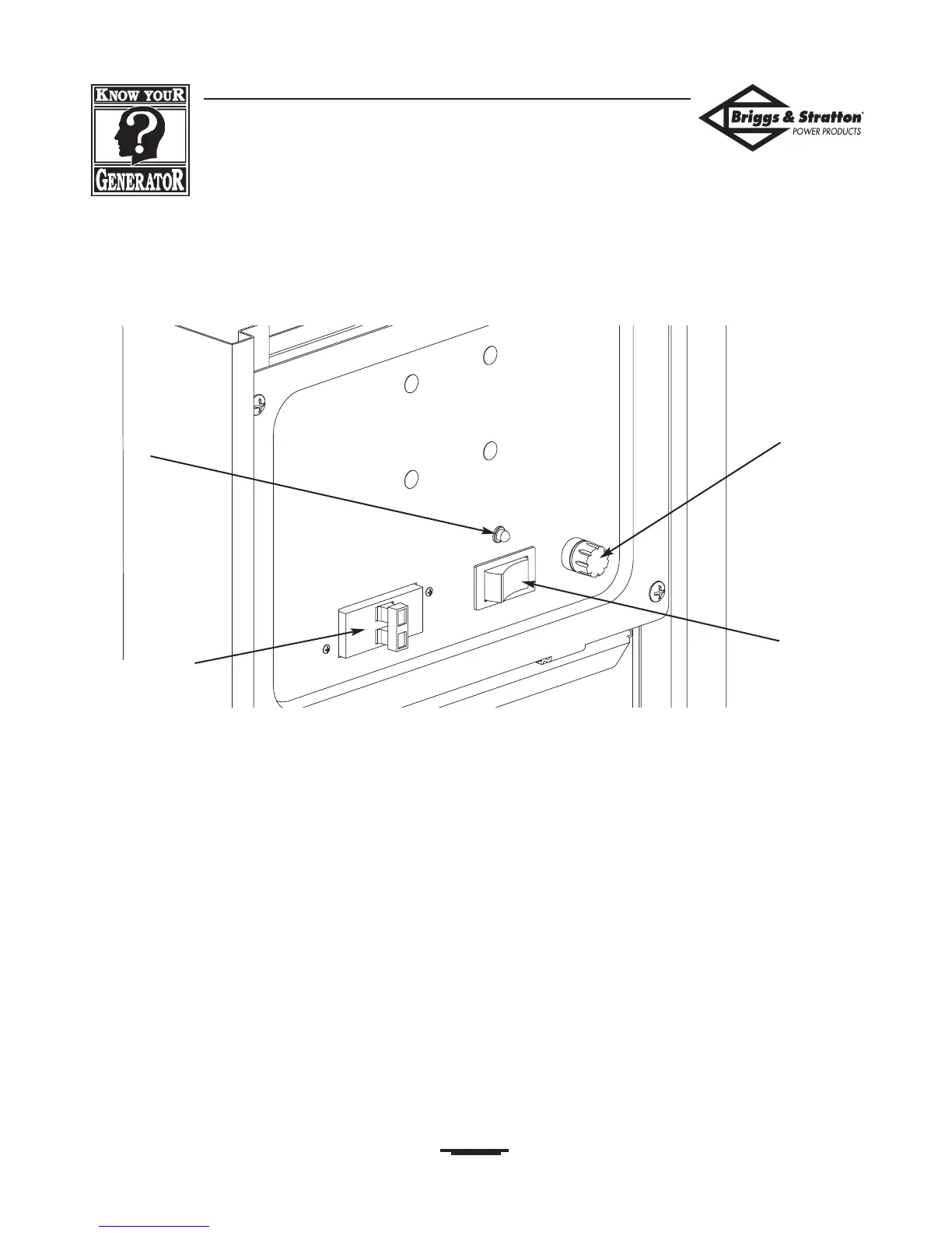
KNOW YOUR CONTROL PANEL
Compare this Control Panel illustration with your generator to familiarize yourself with the location of these important
controls:
Circuit Breaker
LED Light
START/RUN/STOP
Switch
15 Amp Fuse
15 Amp Fuse — Protects the Home Standby Generator
DC control circuits. If the fuse has melted open or was
removed, the engine cannot crank or start. Replace the fuse
using only an identical BUSS AGC 15A fuse.
START/RUN/STOP Switch — This three-position
switch is used as follows:
•“START” position starts the generator.
•“RUN” position is the normal operating mode.Allows
you to start generator from a remote switch.
•“STOP” position turns off generator.
Circuit Breaker — Protects the system from over-
current conditions and must be in the “On” position to
supply power to the Transfer Switch.
LED Light — Indicates when generator is running or off.
Circuit Breaker
START/RUN/STOP
15 Amp
Fuse
 Loading...