6
D
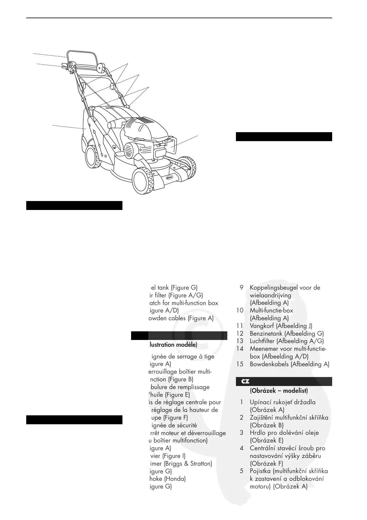
(Abbildung Modell)
D
1 Holmspanngriff (Bild A)
2 Verriegelung Multi-Funktions-
Box (Bild B)
3 Öleinfüllstutzen (Bild E)
4 Zentralverstellschraube für
die Schnitthöheneinstellung
(Bild F)
5 Sicherheitsbügel
(Motorstop und Entriegelung
Multi-Funktions-Box) (Bild A)
6 Hebel (Bild I)
7 Primer (Briggs & Stratton)
(Bild G)
8 Choke (Honda) (Bild G)
9 Kupplungsbügel für den
Radantrieb (Bild A)
10 Multi-Funktions-Box
(Bild A)
11 Fangkorb (Bild J)
12 Benzintank (Bild G)
13 Luftfilter (Bild A/G)
14 Mitnehmer für Multi-Funktions-
Box (Bild A/D)
15 Bowdenzüge (Bild A)
GB
(Illustration of Model)
1 Clamping grip (Figure A)
2 Multi-function box catch
(Figure B)
3 Oil filler pipe (Figure E)
4 Central adjusting screw for
cutting height adjustment
(Figure F)
5 Safety handle (motor stop
and multi-function box release)
(Figure A)
6 Lever (Figure I)
7 Primer (Briggs & Stratton)
(Figure G)
8 Choke (Honda) (Figure G)
9 Coupling link for wheel drive
(Figure A)
10 Multi-function box (Figure A)
11 Grass catcher (Figure J)
12 Fuel tank (Figure G)
13 Air filter (Figure A/G)
14 Catch for multi-function box
(Figure A/D)
15 Bowden cables (Figure A)
F
(Illustration modèle)
1 Poignée de serrage à tige
(Figure A)
2 Verrouillage boîtier multi-
fonction (Figure B)
3 Tubulure de remplissage
d'huile (Figure E)
4 Vis de réglage centrale pour
le réglage de la hauteur de
coupe (Figure F)
5 Poignée de sécurité
(arrêt moteur et déverrouillage
du boîtier multifonction)
(Figure A)
6 Levier (Figure I)
7 Primer (Briggs & Stratton)
(Figure G)
8 Choke (Honda)
(Figure G)
9 Système d'embrayage pour
roues motrices (Figure A)
10 Boîtier multifonction (Figure A)
11 Panier de ramassage
(Figure J)
12 Réservoir à essence (Figure G)
13 Filtre à air (Figure A/G)
14 Entraîneur pour boîtier multi-
fonction (Figure A/D)
15 Câbles Bowden (Figure A)
D
(Afbeelding Model)
NL
1 Steelspangreep (Afbeelding A)
2 Vergrendeling multi-functie-box
(Afbeelding B)
3 Olievulaansluitstuk
(Afbeelding E)
4 Centrale instelbout voor
de maaihoogte-instelling
(Afbeelding F)
5 Veiligheidsbeugel (motorstop
en ontgrendeling multi-functie-
box) (Afbeelding A)
6 Hendel (Afbeelding I)
7 Startdrukknop
(Briggs & Stratton)
(Afbeelding G)
8 Choke (Honda)
(Afbeelding G)
9 Koppelingsbeugel voor de
wielaandrijving
(Afbeelding A)
10 Multi-functie-box
(Afbeelding A)
11 Vangkorf (Afbeelding J)
12 Benzinetank (Afbeelding G)
13 Luchtfilter (Afbeelding A/G)
14 Meenemer voor multi-functie-
box (Afbeelding A/D)
15 Bowdenkabels (Afbeelding A)
CZ
(Obrázek – modelist)
1 Upínací rukojeť držadla
(Obrázek A)
2 Zajištění multifunkční skříňka
(Obrázek B)
3 Hrdlo pro dolévání oleje
(Obrázek E)
4 Centrální stavěcí šroub pro
nastavování výšky záběru
(Obrázek F)
5 Pojistka (multifunkční skříňka
k zastavení a odblokování
motoru) (Obrázek A)
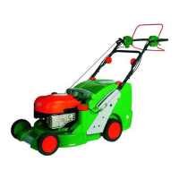
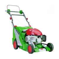
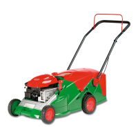
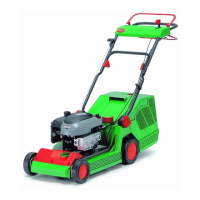
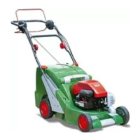
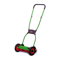
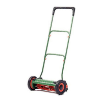
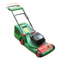
1. Funktionsteile – Functional Parts – Pièces de fonctionnement – Functieonderdelen – Funkční díly
1
15
14
13
5
9
10
A
 Loading...