36
VII. Electrical
A. Install Boiler Wiring
1. Knockdown boilers only. Locate wiring harnesses in
Combination Boiler Parts and Control Carton. Refer
to Table 10 and connect wiring as shown on the
appropriate wiring diagram.
2. Connect supply wiring and electrically ground boiler
in accordance with requirements of authority having
jurisdiction, or in absence of such requirements the
National Electrical Code, ANSI/NFPA 70 and/or
CSA C22.1 Electrical Code.
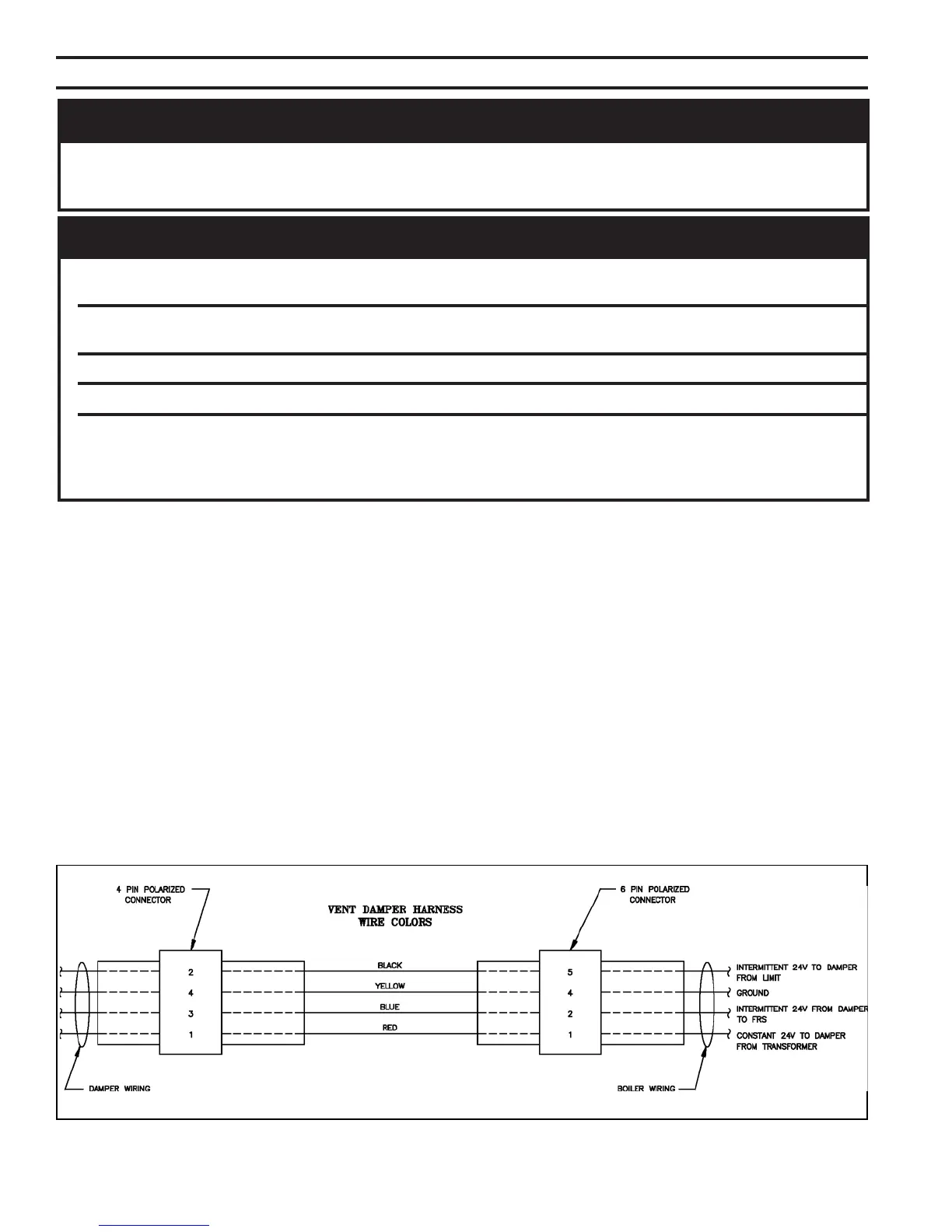
B. Wire Vent Damper (if used; required on 805, optional
on 806-810). See Figure 28.
1. Attach Vent Damper Harness to mounting hole in
Jacket Left Side Panel. Install Cable Clamp around
flexible conduit and attach to Jacket Top Panel.
Figure 30: Vent Damper Schematic Wiring Diagram
REGNAD
ecivresronoitallatsnignitpmettaerofebderewopnuerasnoitcennoclacirtcelellaerussaylevitisoP
sexoblacirtcelellatuokcoL.gnidliubroreliobehtfosnoitcennocrostnenopmoclacirtcelefo
.ffodenrutsirewopecnokcoldaphtiw
GNINRAW
lacisyhpsuoiresnitluseryamreliobehtotsnoitcennoclacirtceleeriwylreporpoteruliaF
.mrah
erofebffosirewopllaerusekaM.ecruosenonahterommorfebyamrewoplacirtcelE
.krowlacirtceleynagnitpmetta
.tcennocsiddesufdezisylreporpahtiwdetcetorpebtsumreliobhcaE
.slortnocgnitareporoytefasynaevitareponiekamrotuopmujreveN
reliobhcaE.ylnosesoprupecnereferroferalaunamsihtnideniatnocsmargaidgniriwehT
ehtdnamargaidsihtotrefeR.roodtnorfehtotdehcattamargaidgniriwahtiwdeppihssi
gniriwllawollofdnadnatsrednu,daeR.reliobehthtiwdesuslortnocynafomargaidgniriw
.slortnocehthtiwdeilppussnoitcurtsni
2. Remove factory installed Jumper Plug from Vent
Damper Receptacle on Vestibule Wiring Harness
and discard.
3. Plug Vent Damper Harness Plug into Vent Damper
Receptacle. See Figure 28.
C. Install thermostat. Locate on inside wall approximately
4 feet above floor. Do not install on outside wall, near
fireplace, or where influenced by drafts or restricted air
flow, hot or cold pipes, lighting fixtures, television, or
sunlight. Allow free air movement by avoiding
placement of furniture near thermostat.
Set heat anticipator to match control system
requirements. Refer to Table 9.
D. Wire thermostat. Provide Class II circuit between
thermostat and boiler. Refer to appropriate wiring
diagram for control system being used.
 Loading...