11
5. Electrical connection
Electrical connection must be carried out
by a qualified electrician in accordance
with local regulations.
Follow all safety standards.
The unit must be properly earthed (grounded).
Follow the instructions in the wiring diagram
hereto attached.
Once the electrical connection has been
completed, remove any pieces of wire, sheath,
washers or any other foreign bodies that may be
found inside the electric control panel.
6. Starting
When the control unit is turned on, the pump is on
STOP (factory setting).
After making the connections, close the control
unit and turn on the power by turning the main
door-lock switch.
If the phases on the power line have not been
connected correctly, the display shows the alarm
message PHASE SEQUENCE ERROR. Change
the power line connections.
The first line of the display shows the message
PUMP STOPPED and the second line shows
wh xxxx (working hours) and the power line
voltage.
Before starting the pump, access the programming
parameter menu ( PROG pushbutton), select
the dialogue language and then change the factory
settings in the various parameters (see paragraph
3.1.1.). When the settings have all been changed,
press the PROG pushbutton and exit the
programming page.
The display shows the message PUMP
STOPPED, wh (working hours) and the power line
voltage.
To start the pump, press the AUT-STOP
pushbutton and the pump switches to automatic
functions.
The top line shows the message PUMP ON
AUTOMATIC and the pump works according to
the signals from the pressure switch or float
switch.
When the pump is working, the top line shows the
PF value and the current intake by the motor; the
bottom line shows the working hours and the
power line voltage.
6.1. Inversion of the direction of
rotation
Check the direction of rotation .
For this test, use AUT/STOP pushbutton or
MAN pushbutton.
Start the pump with the gate valve regulated
to minimum aperture and wait until the delivery
pipe is completely free of air.
For this purpose, with the gate valve at half-open
aperture position, check the pressure (with the
pressure gauge) or flow rate (sight check). Switch
the power off, reverse the connections of two
phases of the pump in the control panel, re-start
and check the pressure or flow rate capacity
again.
The correct direction of rotation will provide a
considerably greater and easily distinguishable
pressure and delivery capacity.
7. Operation
The pump can work automatically with the signals
from the pressure switch (pressure circuit) or a
float (tank filling).
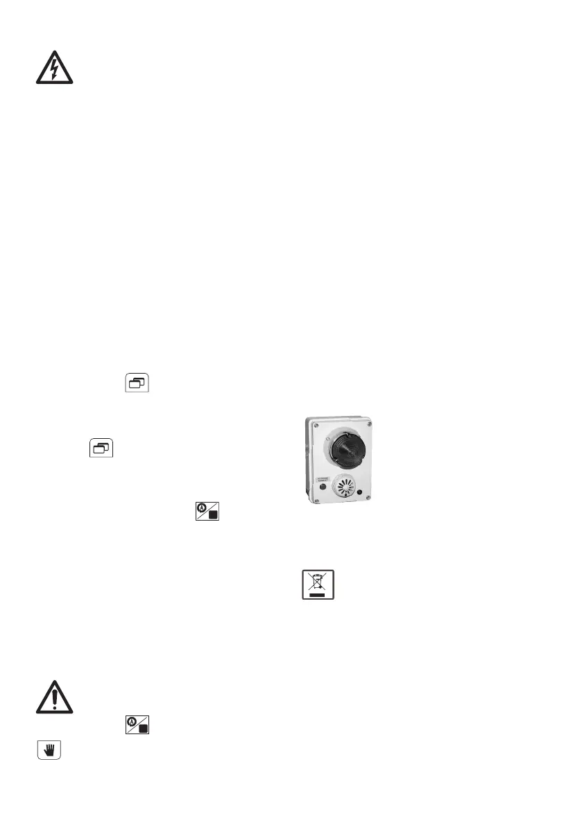
8. Accessories
8.1. RA 100
Control panel for remote alarm
Dimensions: 110x150x70
Power supply: 220-230 V single-phase
Signals all PFC-T control panel malfunctions
detected.
5-Watt flashing red light plus 75 dB - 3600 Hz
acoustic alarm, for use in areas of loud noise,
positioned in such a way as to be visible from a
distance.
The control panel is fitted to an energized panel
led and an alarm reset pushbutton.
RA 100
9. Disposal
European Directive 2012/19/EU (WEEE)
Observe the local regulations and dispose
of any control gear accordingly. This
product contains electrical and electronic
components and should be disposed of
accordingly.
istr_P473_08_PFC_T_calpeda_istr_P473 15/01/19 09:17 Pagina 11
 Loading...