E
≤60
41
100
p. 10 - Manual FA01007-EN - v. 1 - 10/2017 - © CAME S.p.A. - "Translated original instructions"
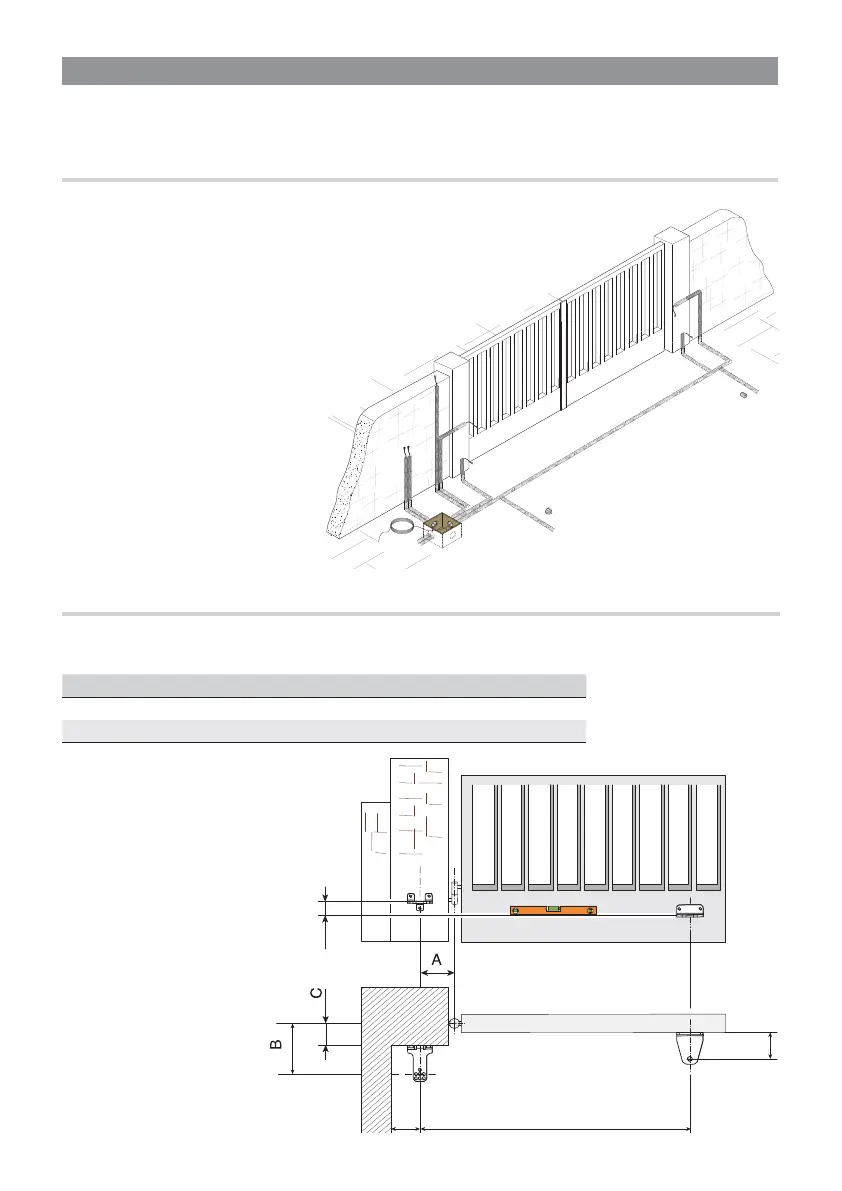
Opening (°) A (mm) B (mm) C (mm) E (mm)
90 130 110 - 170 0 - 60 750
115 150 110 - 160 0 - 50 750
FASTENING THE BRACES
Establish the gate bracket fastening point and find the bracket's fastening point to the post, while respecting
the quotas shown in the drawings and tables.
⚠ The greater the gate leaf's
opening angle, the greater the
opening speed and the slower
is the gearmotor's thrust.
The smaller the gate leaf's
opening angle, the slower the
opening speed and the greater
is the gearmotor's thrust.
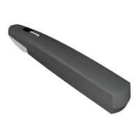
INSTALLATION
The following illustrations are mere examples in that the space for anchoring the operator and accessories
varies depending on the installation area. It is up to the installer to find the most suitable solution.
CORRUGATED TUBE LAYING
Set up the junction boxes and corrugated tubes you will need to make connections coming from the junction pit.
To connect the gearmotor we suggest a Ø 60 mm corrugated tube. Whereas for
the accessories we suggest Ø 25 mm tubes.
The number of tubes depends on the type of system and the
accessories you are going to fit.
 Loading...