9
General Notes
• Read the instructions carefully before beginning the
installation and carry out the actions as specied by the
maker;
• The installation, programming, putting into operation
and maintenance of the product must be carried out only
by qualied technical personnel, correctly trained with
regard to respecting the regulations in force, including the
implementation of accident prevention measures;
• Before carrying out any cleaning or maintenance operation,
disconnect the device from the power supply;
• The equipment must be destined solely for the use for
which it was expressly designed.
• The manufacturer declines all liability for any damage as
a result of improper, incorrect or unreasonable use.
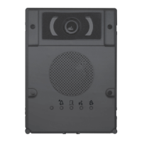
Technical features A B
Entry panel
Type DMC/08 DMVC/08
12V DC power supply 14 ÷ 18
Current consumption (mA) 150 275
Consumption in stand-by mode
(mA)
110 110
Dimensions (mm) 95x130x35
Operating temperature (°C) -15 ÷ +50
Storage temperature (°C) -25 ÷ +70
Video standard PAL
Resolution (pixel) 680x512
Minimum lighting (LUX) 1
Accessories
Type DMC/08 DMVC/08
Solenoid lock absorption (mA) 500
Absorption VZS/308C (mA) 8
Absorption with keypad
backlight (mA)
20
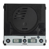
Installation C
• Remove the terminal board covers as shown in gure ①.
• Remove the terminal board, make the connections to the
buttons using the additional modules (see “Connection
examples”); reposition the terminal in its housing as shown
in gure ②, paying attention to the direction in which they
are placed.
• Remove the microphone from its housing as shown in
gure ③.
• Fasten the audio/video module to the xing plate, inserting
the small glass in between, as shown in gure ④.
• Position the microphone in the chosen position, keeping
in mind that the maximum cable length connecting the
module to the microphone is 300 mm.
• Position the DMRFID module in the chosen position, keep-
ing in mind that the maximum cable length connecting the
module to the DMRFID is 150 mm ⑤.
Led functions and adjustments D
Adjustments ①
loudspeaker audio
microphone audio
solenoid lock 1-10 s. (default 1 s)
Signals ②
- Red - Call in progress
- Green - Door open
- Yellow - Conversation in progress
- Blue - System busy
Function of terminals E
Terminal board ①
– Ground
Entry panel enabling output (active towards ground)
– Ground
Door contact input (NC)
Door lock release button (NA)
–
Solenoid lock 12 V - 1 A max
+
Power supply 14-18 VDC
–
A
Audio
D
+
Data line
–
V
+
Video Signal
–
Function of connectors E
② MIC: Connector for microphone.
③ PUSH BUTTON: Connector for 1-4 call push buttons.
④ KEYBOARD: Connector for numeric keypad.
⑤ RFID: Connector for proximity reader module DMRFID.
⑥ VZS: Connector for VZS/308C module.
⑦ MINI USB: Programming connector.
⑧ SW4: Line length selector.
Conguration of line length selector F
Connection examples DMC/08 G
Connection examples DMVC/08 HIJ
Connection example K
A maximum of 11 VZS/308C (5÷92 calls) can be connected
to the DMVC/08 or DMC/08 module ①.
Cabling diagram for PUSH BUTTON connector ②
Reference Colour Meaning
C Black Common
1 Brown Call 1
2 Red Call 2
3 Orange Call 3
4 Yellow Call 4
Diagram for connection of a generic keypad
or a DMRFID reader L
① Row A
② Row B
③ Row C
④ Row D
⑤ Column 1
⑥ Column 2
⑦ Column 3
⑧ Backlight
Initial programming in systems with a
single entry panel with buttons M
Entering “programming” mode.
Press the PROG key on the power supplier ① until the
PROG LED turns on. The entry panel LEDs turn on as shown
in the gure ②.
NOTE. If the PROG LED turns off suddenly, this indicates
a malfunction in the connection between the power
supplier and the entry panel. Check the connections
and return to programming.
Wait 5 seconds for the autotest to finish. Repeat the
operation a second time ③. Check that the entry panel
conguration is as illustrated in gure ④.
Programming the call keys.
Lift the handset (if present) of the receiver that you want to
programme ⑤ and then press the door lock release and
AUX2 buttons ⑥. On the entry panel, press the call key to
be associated with the receiver ⑦: an acoustic signal will
conrm that the setting was stored. Hang up the handset
⑧ again, if necessary and continue, repeating the same
operations for the other receivers.
Exiting Programming ⑨.
Briey press the PROG key on the power supplier: the PROG
LED and entry panel LEDs will turn o.
NOTE. If no action is performed, the procedure will
automatically end after 30 minutes.
Initial programming in systems with more
than one entry panel with buttons N
Entering “programming” mode.
Press the PROG key on the power supplier ① until the
PROG LED turns on. The entry panel LEDs turn on as shown
in gure ②.
NOTE. If the PROG LED turns off suddenly, this indicates
a malfunction in the connection between the power
supplier and the entry panel. Check the connections
and return to programming.
Wait 5 seconds for the autotest to finish. Repeat the
operation a second time ③. Check that the entry panel
conguration is as illustrated in gure ④.
Programming the call keys.
The operation may only be performed from the entry panel
with the LED o (1 in g. ④); to change the entry panel
from which the call programming is performed, press one
of the rst 4 call key positions for at least 3s.
Lift the handset (if present) of the receiver that you want to
programme ⑤ then press the door lock release and
AUX2 buttons ⑥. On the entry panel, press the call key to
be associated with the receiver ⑦: an acoustic signal will
conrm that the setting was stored. Hang up the handset
⑧ again, if necessary and continue, repeating the same
operations for the other receivers.
Exiting “programming” mode ⑨.
Briey press the PROG key on the power supplier: the PROG
LED and entry panel LEDs will turn o.
NOTE. If no action is performed, the procedure will
automatically end after 30 minutes.
Procedure for reprogramming a call with
entry panels with buttons O
Entering “programming” mode.
Press the PROG key on the power supplier ① until the
PROG LED turns on. The entry panel LEDs turn on as shown
in gure ②.
Reprogramming the call keys.
The operation may only be performed from the entry panel
English
 Loading...