31
Electrical data (cont)
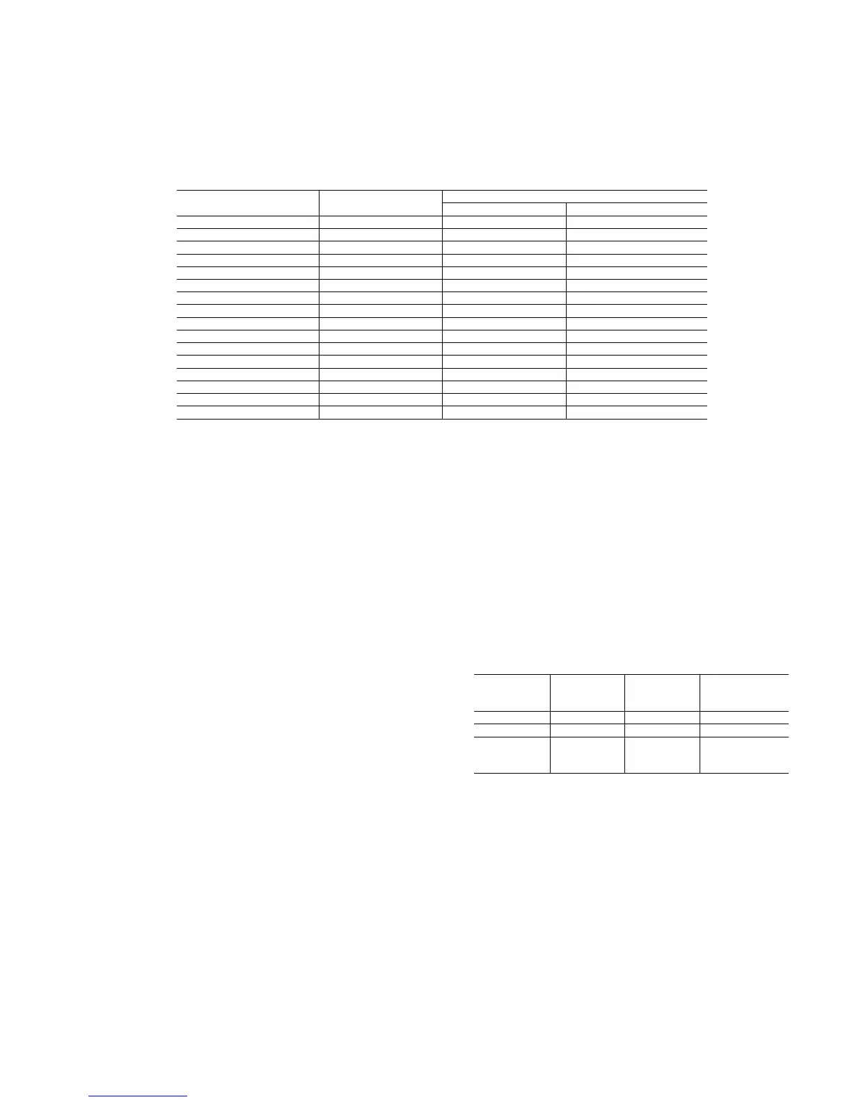
CONDENSER FAN DATA
CONDENSER FAN
UNIT SIZE 30GTN,GTR
GBN,GBR
NOMINAL VOLTAGE
(V-Ph-Hz)
TOTAL (Quantity) FLA (ea)
050 400-3-50 4 3.4
060 400-3-50 6 3.4
070 400-3-50 6 3.4
080 400-3-50 6 3.4
090 400-3-50 6 3.4
100 400-3-50 8 3.4
110 400-3-50 8 3.4
150 400-3-50 12 3.4
175 400-3-50 12 3.4
200 400-3-50 12 3.4
300A 400-3-50 12 3.4
300B 400-3-50 12 3.4
350A 400-3-50 12 3.4
350B 400-3-50 12 3.4
400A 400-3-50 12 3.4
400B 400-3-50 12 3.4
LEGEND AND NOTES FOR ELECTRICAL DATA
LEGEND
FLA - Full Load Amps (Fan Motors)
ICF - Maximum Instantaneous Current Flow during
starting (the point in the starting sequence where the
sum of the LRA for the starting compressor, plus the
total RLA for all running compressors, plus the total
FLA for all running fan motors is maximum)
LRA - Locked Rotor Amps
MCA - Minimum Circuit Amps (for wire sizing) – complies
with NEC Section 430-24
MOCP - Maximum Overcurrent Protection Device Amps
Rec Fuse- Recommended dual-element fuse amps: 150% of
largest size compressor RLA plus 100% of sum of
remaining compressor RLAs. Size up to the next
larger fuse size.
RLA - Rated Load Amps (compressors)
*Units are suitable for use on electrical systems where voltage
supplied to the unit terminals is not below or above the listed
minimum and maximum limits. Maximum allowable phase
imbalance is: voltage, 2%; amps 10%.
NOTES:
1. All units/modules have single point primary power connection.
(Each unit/module requires its own power supply). Main
power must be supplied from a field-supplied disconnect.
2. The unit control circuit power (230 v, single-phase) must be
supplied from a separate source through a field-supplied
disconnect. The control circuit transformer accessory may be
applied to power from primary unit power.
3. Crankcase heaters are wired into the control circuit so they
are always operable as long as the control circuit power
supply disconnect is on, even if any safety device is open,
and the unit ON/OFF switch is in the OFF position.
4. Units have the following power wiring terminal blocks and
parallel conductors:
UNIT SIZE
30GTN,GTR,
GBN,GBR
VOLTAGE
TERMINAL
BLOCKS
PARALLEL
CONDUCTORS
050 to 070 400 1 3
080 to 110 400 1 3
150 to 200,
300A/B to
400A/B
400 2 6
5. Maximum incoming wire size for each terminal block is 500
kcmil.
6. Power draw control circuits include crankcase heaters.
Each compressor has a crankcase heater which draws 180
watts of power.
 Loading...