SG-38MARB-01 Specifications subject to change without notice. 13
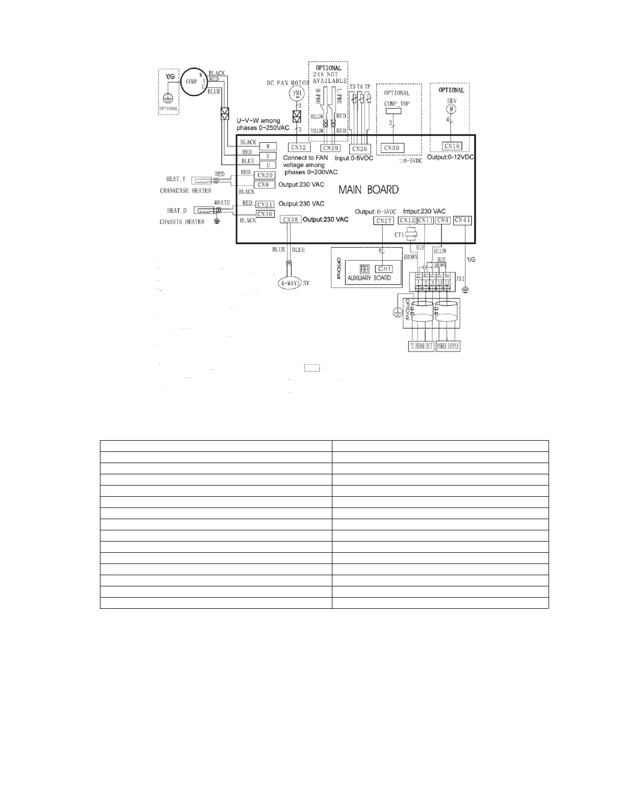
WIRING DIAGRAMS (CONT)
Fig. 13 — Wiring Diagram Sizes 24-36K (208/230V)
Table 12 — Wiring Diagram - Sizes 24-36K (208/230V)
CODE PART NAME
JX1 Terminal Block
COMP_TOP Compressor Top OLP Temperature Sensor
EEV Electronic Expansion Valve
FM1 DC Fan Motor
COMP Compressor
HEAT_Y Crankcase Heater
CT1 AC Current Detector
H-PRO High Pressure Switch
L-PRO Low Pressure Switch
SV Reverse Valve
TP COMP. Discharge Temperature Sensor
T3 Coil Temperature Sensor
T4 Outdoor Ambient Temperature Sensor
HEAT_D Chassis Heater
NOTE
This symbol indicates that
the element is optional.
NOTE
This symbol indicates that
the element is optional.
The actual shape shall prevail.
Input

 Loading...