10
INSTALL ALL POWER AND INTERCONNECTING
WIRING TO OUTDOOR UNITS
1. Mount the outdoor power disconnect.
2. Run the power wiring from the main box to disconnect per
NEC and local codes.
3. Remove the field wiring cover from the unit by loosening
the screws.
4. Remove the caps on the conduit panel.
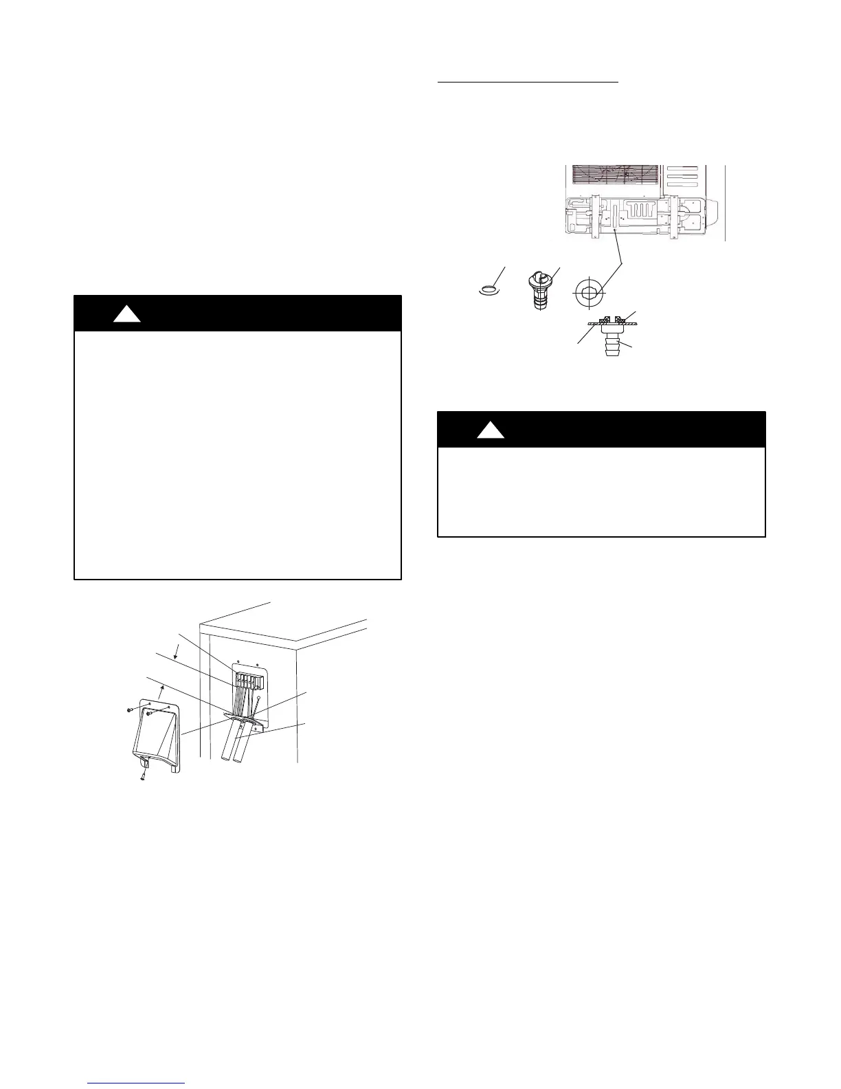
5. Connect the conduit to conduit panel (see Fig. 11).
6. Properly connect both the power supply and control lines
to the terminal block per the connection diagram for the
appropriate unit capacity and voltage.
7. Ground the unit in accordance with NEC and local electrical
codes.
8. Use the lock nuts to secure the conduit.
9. Reinstall the field wiring cover.
CAUTION
!
EQUIPMENT DAMAGE HAZARD
Failure to follow this caution may result in equipment
damage or improper operation.
S Be sure to comply with local codes while running wire
from indoor unit to outdoor unit.
S Every wire must be connected firmly. Loose wiring may
cause the terminal to overheat or result in unit
malfunction. A fire hazard may also exist. Therefore,
ensure all wiring is tightly connected.
S No wire should be allowed to touch the refrigerant
tubing, compressor or any moving parts.
S Disconnecting means must be provided and shall be
located within sight and readily accessible from the air
conditioner.
S Connecting cable with the conduit shall be routed
through hole in the conduit panel.
Over 1.57" (40mm)
Terminal Block
Conduit panel
Conduit
Outdoor unit
A07455
Fig. 11 - Field Wiring
DRAIN CONNECTIONS
Install drains must meet local sanitation codes.
Install the outdoor unit drain joint
Fit the seal into the drain joint, then insert the drain joint into the
base pan hole of the outdoor unit. Rotate 90
_ to securely assemble
them. Connect the drain joint with an extension drain hose to avoid
condensate from draining off the outdoor unit during heating
mode.
Seal
Base pan hole
Drain joint
Seal
Base pan
Drain
joint
Fig. 12 - Drain Joint
Images are for illustration purposes only.
CAUTION
!
In cold climates, ensure the drain hose is as vertical as
possible to ensure swift water drainage.
If water drains too slowly, it can freeze in the hose and flood
the unit.

 Loading...