38MHRC: Service Manual
Manufacturer reserves the right to change, at any time, specifications and designs without notice and without obligations.
32
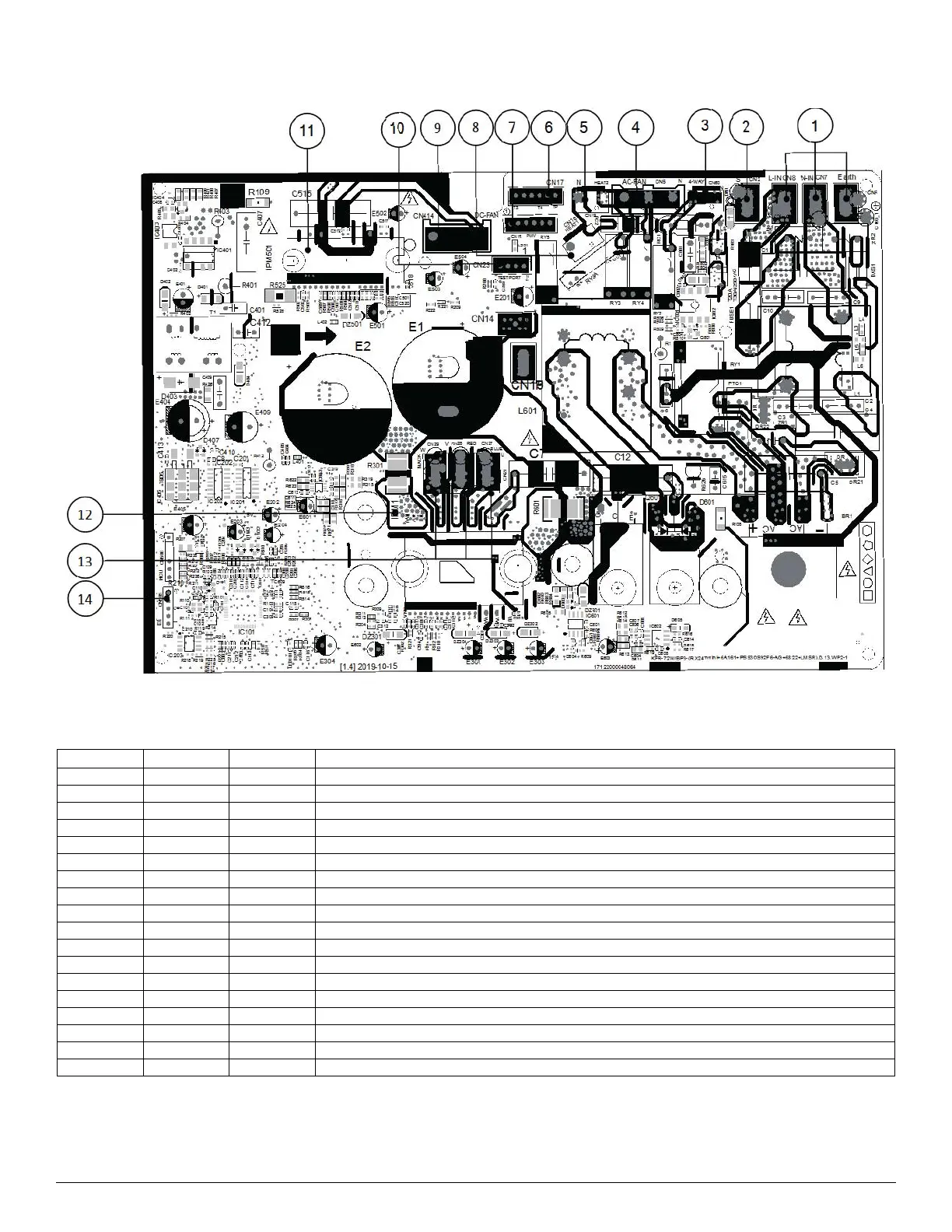
PCB DIAGRAMS (COOLING ONLY) (CONT)
A210595
Fig. 37 —Size 24K (208/230V)
Table 15 — LED Codes
No. Name CN# Meaning
1 Power Supply CN6 Earth: connect to Ground
CN7 N_in: connect to N-line (208-230V AC input)
CN8 L_in: connect to L-line (208-230V AC input)
2SCN2 S: connect to indoor unit communication
34-WAYCN60 Connect to 4 way valve, 208-230V AC when is ON.
4AC-FANCN5 Connect to AC fan
5HEAT2CN19 Connect to chassis heater, 208-230V AC when is ON
6 TP T4 T3 CN17 Connect to pipe temp. sensor T3, ambient temp. sensor T4, exhaust temp. sensor TP
7PMVCN18 Connect to Electric Expansion Valve
8HEAT1CN16 Connect to compressor heater, 208-230V AC when is ON
9 DC-FAN CN414 Connect to DC fan
10 TESTPORT CN23 Used for testing
11 FAN_IPM IPM501 IPM for DC fan
12 COMP_IPM IPM1 IPM for compressor
13 U CN27 Connect to compressor
V CN28 0V AC (standby)
W CN29 200-300V AC (running)
14 EE_PORT CN505 EEPROM programmer port

 Loading...