40MBFAQ: Installation Instructions
Manufacturer reserves the right to change, at any time, specifications and designs without notice and without obligations.
9
INTERCONNECTING PIPING
Table 7 — Tightening
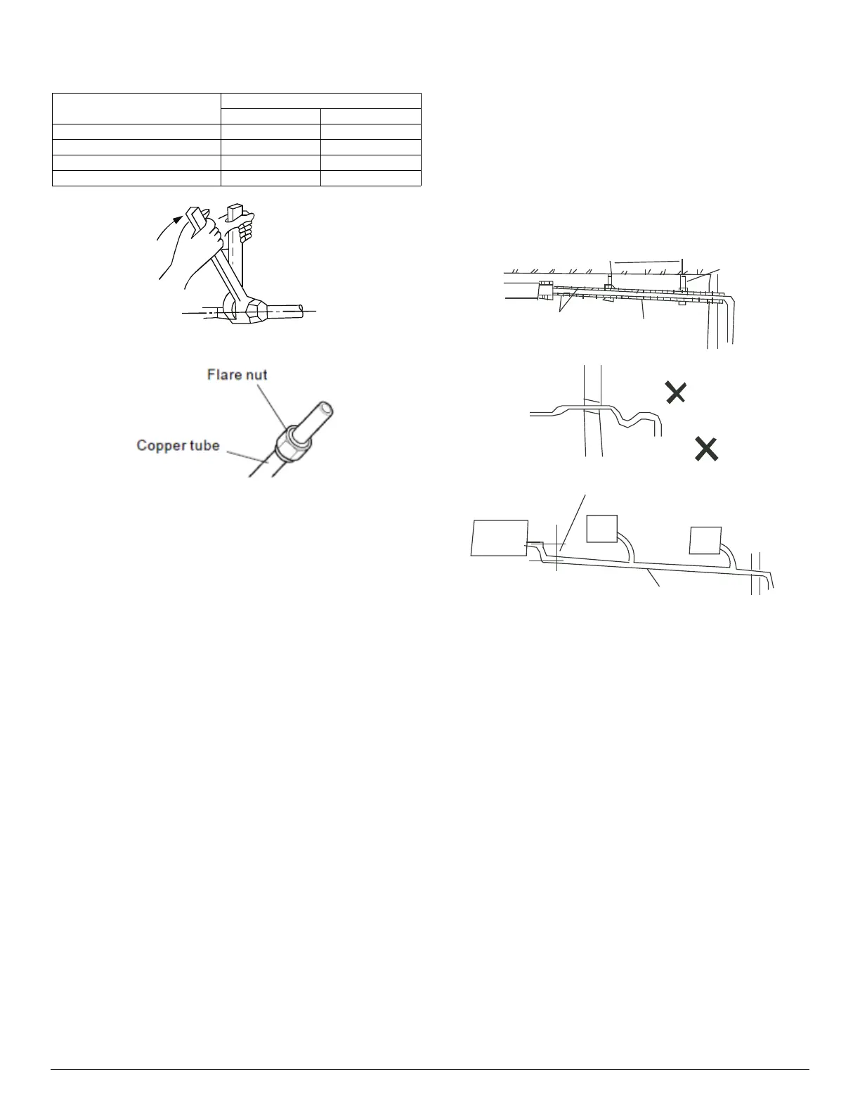
Fig. 10 — Tighten
Fig. 11 — Flare Nut and Copper Tube
CONDENSATE DRAIN CONNECTION
The unit is supplied with a drain connection to connect the drain piping. When
installing condensate piping, follow these recommendations:
• Condensate piping should slope downward in the direction of the condensate
flow, with a minimum gradient of 1 in. per 100 inches.
• When multiple units are connected to a common condensate drain, ensure the
drain is large enough to accommodate the volume of condensate from all units.
It is also recommended to place an air vent in the condensate piping to prevent
any air locks.
• Condensate piping must not be installed where it may be exposed to freezing
temperatures.
Fig. 12 —Condensate Flow
PIPE DIAMETER INCH (MM)
TIGHTENING TORQUE
FT-LB N - M
Ø1/4” (6.35) 10 to 13 13.6 to 17.6
Ø3/8” (9.52) 24 to 31 32.5 to 42.0
Ø1/2” (12.7) 37 to 46 50.1 to 62.3
Ø5/8” (15.88) 50 to 60 67.7 to 81.3
1.5m~2m
Insulating
material
Downward declivity
lower than 1/100
Bend
S shape
VP30
lower than 1/100
Put as deep as possible
(about 10cm)
 Loading...