42 GW
GB - 10
B
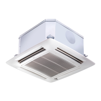
Motorized valve and control
Automatic operation position
A Thermo-electric valve head
B Valve body
Instructions for field supplied valves
Water connection
• Install valves following manufacturer's instructions; refer to the
relevant figures for connection to the unit.
• Carefully insulate pipes, valve assemblies and coil connections
(cold water side) to avoid condensation forming on the pipes
and dripping on the false ceiling.
Electrical wiring
• Connect the room control following instructions for the control
used.
WARNING:
Pass cables through the control panel cable-conduit.
• Connect valves as per the following instructions, using the
wiring diagram in this chapter.
• Valves, closing the unit water inlet when there is no
power supply, must be used.
A
Operation of the thermo-electric valve
• This 3-way valve is an ON-OFF type with a very slow stroke.
It is not a modulating valve so it has no PTC.
This valve is driven, as a sensible element, by the ambient
thermostat of the “cassette” unit.
• The thermo-electric valve is normally closed towards the coil
and open towards the bypass.
When the room temperature does not satisfy the thermostat,
an electric heater activates the heating of a thermostatic
element which causes the down-stroke of the piston; the
valve opens after about 3 minutes about to allow water to
circulate in the coil.
• If the room temperature satisfies the thermostat or if the
electric power has been switched off, the valve is closed after
about 3 minutes towards the coil and is opened towards the
bypass.
• If an emergency occurs, the valve may be manually opened,
removing the electric head, unscrewing the ring nut.
When the emergency ends, remember to reset the valve to
automatic operation, repositioning the electric head;
failure to do this can result in condensate formation due
the water pipes, even if the unit is switched off.
Fan speed
H = high speed
M = medium speed
L = low speed
Heat
Cool
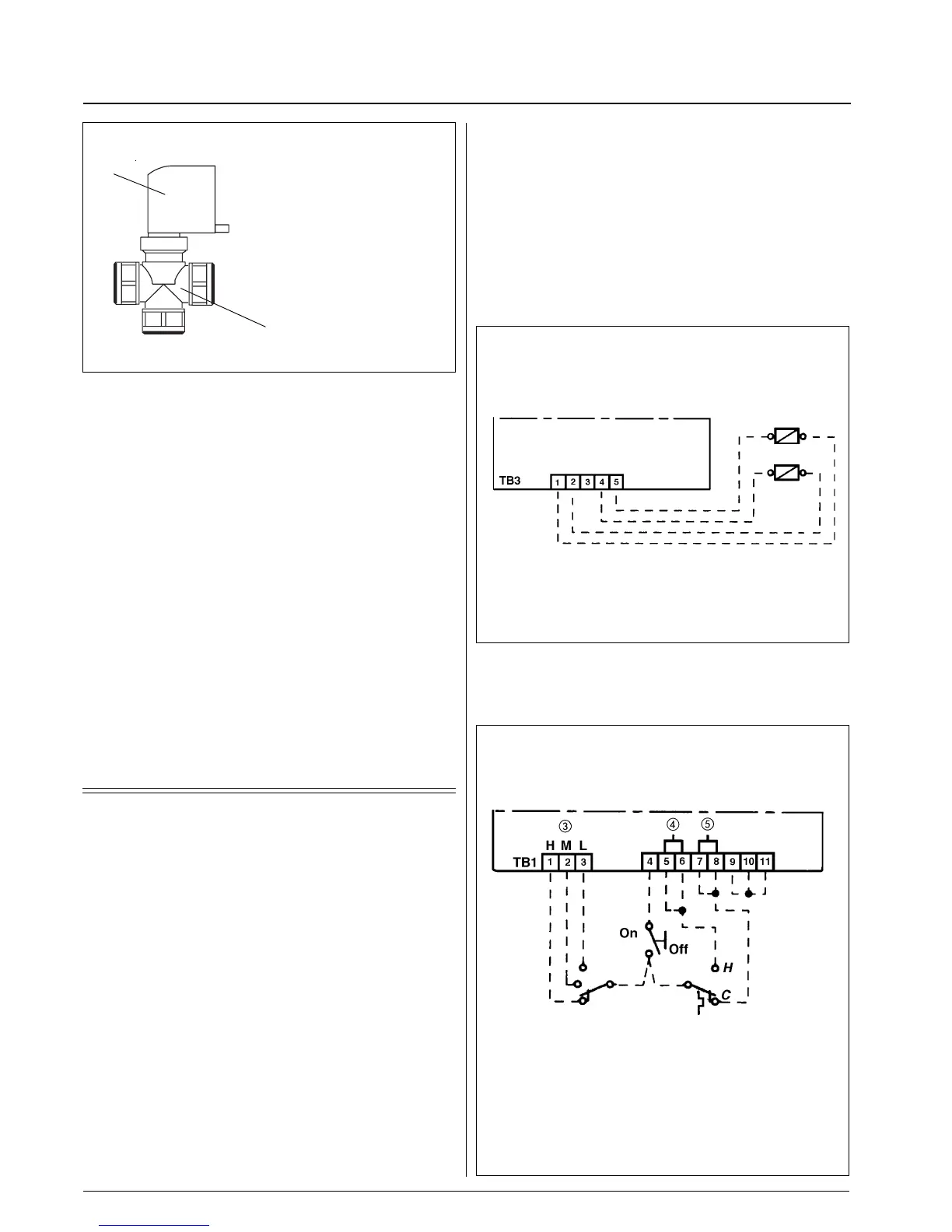
230V valve connection or
230V valve relay connection
H Heating valve or heating valve relay
C Cooling valve or cooling valve relay
ON-OFF valves (230V)
• In this case the cold water valve must be controlled by the ON-
OFF signal from terminal 1 of TB3 and the hot water valve from
terminal 2 of TB3.
ON-OFF valves with other voltages than 230V
• If a room control listed in the accessories table is used, follow
the instructions in the previous paragraph and install two
230V relay at TB3 terminals 1, 2, 4 and 5 which will control
the valve opening.
• If a low voltage control is used or if the control is not listed in
the accessories table, the connections must be made on the
unit terminal board.
Control connection
C
H

 Loading...