20
Humidi--MiZer
R
Control Connections
Humidi--MiZer – Space RH Controller —
NOTE: The Humidi--MiZer is a factory installed option.
The Humidi--MiZer dehumidification system requires a
field--supplied and --installed space relative humidity
control device. This device may be a separate humidistat
control (contact closes on rise in space RH above control
setpoint) or a combination thermostat--humidistat control
device such as Carrier’s EDGE
R
Pro Thermidistat with
isolated contact set for dehumidification control. The
humidistat is normally used in applications where a
temperature control is already provided (units with
PremierLinkt control).
To connect the Carrier humidistat (HL38MG029):
1. Route the humidistat 2--conductor cable (field--supplied)
through the bushing the unit’s louvered end panel (see
Fig. 39).
2. Route the cable through the snap--in wire tie and up to
the web bushing near the control box.
3. Feed the cable through the bushing and into the
bottom left side of the control box after removing one
of the two knockouts in the corner of the box. Use a
connector to protect the cable as it enters the control
box.
4. Use the connector and the wire tie to reduce any slack
in the humidistat cable to ensure that it will not be
damaged by contact with the condenser coil (see Fig.
39).
5. Use wire nuts to connect humidistat cable to two
PINK leads in the low–voltage wiring as shown in
Fig. 42.
To connect the Thermidistat device (33CS2PPRH--01):
1. Route the Thermidistat multi--conductor thermostat
cable (field--supplied) through the bushing the unit’s
louvered end panel (see Fig. 39).
2. Route the cable through the snap--in wire tie and up to
the web bushing near the control box.
3. Feed the cable through the bushing and into the
bottom left side of the control box after removing one
of the two knockouts in the corner of the box. Use a
connector to protect the cable as it enters the control
box.
4. Use the connector and the wire tie to reduce any slack
in the thermostat cable to ensure that it will not be
damaged by contact with the condenser coil (see Fig.
39).
5. The Thermidistat has dry contacts at terminals D1
and D2 for dehumidification operation (see Fig. 43).
The dry contacts must be wired between CTB
terminal R and the PINK lead to the LTLO switch
with field--supplied wire nuts. Refer to the installation
instructions included with the Carrier Edge
Thermidistat device (Form 33CS--65SI or latest) for
more information.
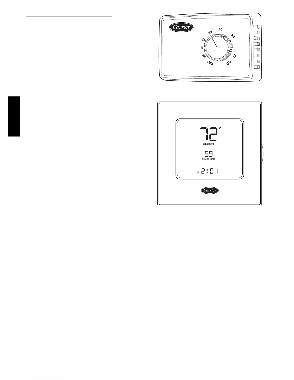
% RELATIVE HUMIDITY
C09295
Fig. 40 -- Accessory Field--Installed Humidistat
®
C09296
Fig. 41 -- EDGE Pro Thermidistat
48TC**16