WIRING SCHEMATICS
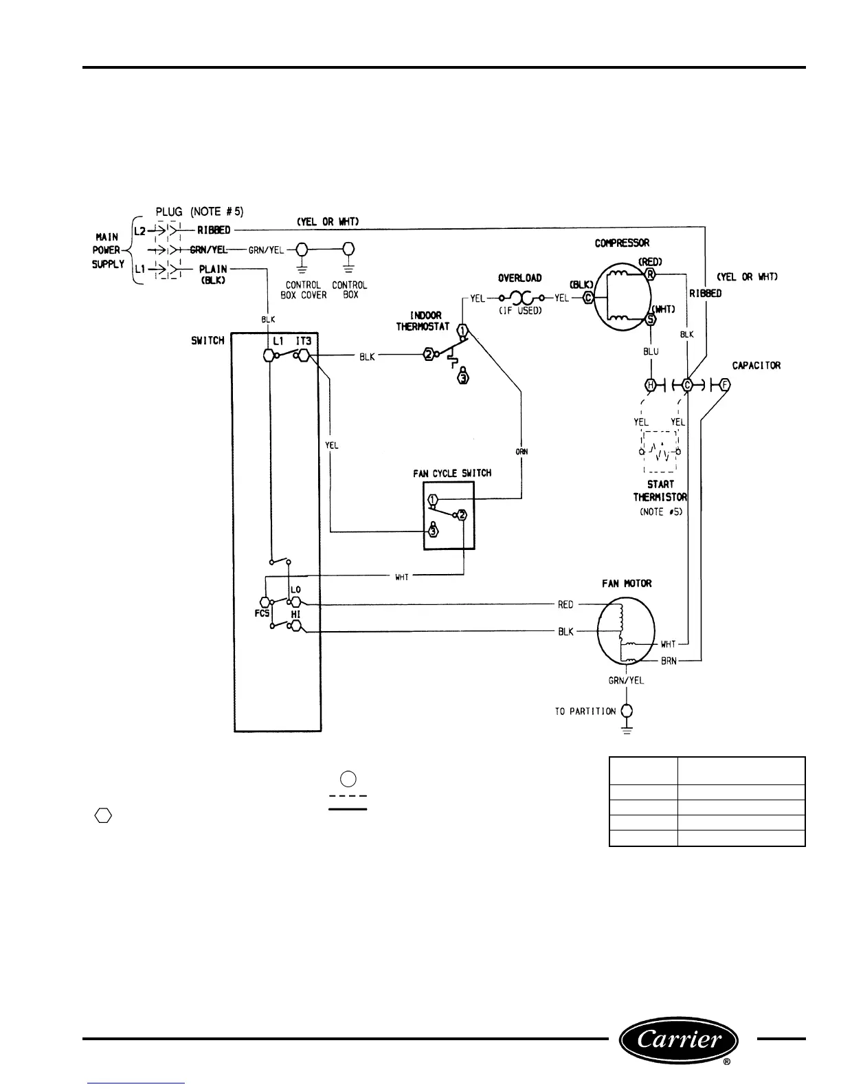
Refer to Figures 83 - 87 for typical 52S unit wiring schematics.
NOTE: Figures 83 - 87 should not be substituted for the schematic
located next to the unit control box.
LEGEND
FCS — Fan Cycle Switch
IT — Indoor Thermostat
L—Power Supply Line
Component Connections (Marked)
Component Connection (Unmarked)
Accessory or Optional Wiring
Factory Wiring
NOTES:
1. Recommended for use on grounded power supply only.
2. Compressor and fan motor thermally protected.
3. Use copper conductors only.
4. All wiring must conform with NEC (National Electrical Code) and local codes.
5. Dashed lines indicate components when used.
FIGURE 83 — WIRING SCHEMATIC; 52SC — 208/230 V AND 265 V AA AND CP UNITS
SWITCH
POSITION
CONTACTS MADE
OFF NONE
FAN L1 TO LO*
LO COOL L1 TO IT3, FCS to LO
HI COOL L1 TO IT3, FCS TO HI
*L1 to MED, some models.
51
 Loading...