58SB0B/58SB1B: Installation, Start–Up, Operating and Service and Maintenance Instructions
Manufacturer reserves the right to change, at any time, specifications and designs without notice and without obligations.
32
connect thermostat wire to R terminal on control board and
re-install blower door.
4. Operate furnace per instruction on door.
5. Verify furnace shut down by lowering thermostat setting below
room temperature.
6. Verify furnace restarts by raising thermostat setting above room
temperature.
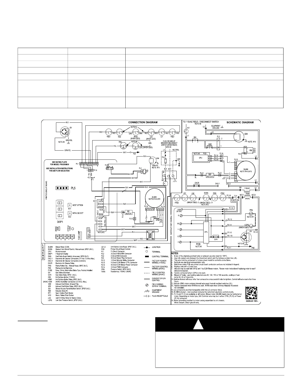
WIRING DIAGRAM
A210787
Fig. 46 – Wiring Diagram
Adjustments
Furnace gas input rate on rating plate is for installations at altitudes up to
2000 ft. (610 M). Furnace input rate must be within +/-2 percent of
furnace rating plate input.
Table 13 – Test Sequence
Display Operating Mode Function
tSt
Test
Confirms start of Component Test mode.
PUr
Purge
Inducer ON for 10 seconds before next stage. Inducer remains ON for test duration.
HSi
Hot Surface Igniter
Hot Surface Igniter ON for 15 seconds, then OFF.
Fn
Fan
Blower ON at 50% torque for 10 seconds, then OFF.
End
End Test
All component OFF except for Inducer for 10 seconds. Display returns to
iDl. If a
thermostat input is detected or fault condition activates during the test sequence, control
will abort and display
End for 6 seconds.
Err
Error
Displayed if component test is not able start. Check for thermostat inputs or faults, and
system status is Idle (
iDl).
WARNING
!
FIRE HAZARD
Failure to follow this warning could result in injury, death and/or
property damage.
DO NOT bottom out gas valve regulator adjusting screw. This can
result in unregulated manifold pressure and result in excess overfire and
heat exchanger failures.

 Loading...