GB - 9
30RA/30RH Puron
ENGLISH
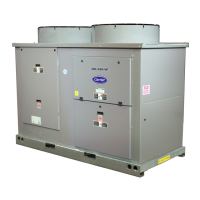
Remove electric box cover.
Connect the wires to the terminals according to the wiring diagram
and firmly tighten.
• The characteristics of the available power supply must
correspond to the unit nameplate specifications.
• The voltage must be within the limits indicated in the technical
data table.
• The imbalance between voltage phases must always be less
than 2%.
• WARNING:
If the unit operates at a voltage outside the limits given in Table
VIII or with a phase imbalance above 2%, this constitutes
improper use and may affect the warranty.
If the phase imbalance is higher than 2%, contact the local
electricity board immediately.
• Electric wiring must be in accordance with data indicated in this
manual and the wiring diagram and conform to applicable local
and national regulations.
• Ensure that mains supply connection is made through a switch
that disconnects all poles, with contact gap of a least 3 mm.
• The mains supply connecting cable must be H07 RN-F (or
higher) type, synthetic rubber insulation with Neoprene coating,
according to EN 60335-1 and HD277.S1 codes.
IMPORTANT:
• Make earth connection prior to any other electrical
connections.
• Earthing is required by law.
The installer must earth the unit using the terminal marked
with the international earthing symbol.
• Before connecting the supply cable to the line, locate line
(L), lines (L1-L2-L3) and neutral N. Then make connections,
as indicated in the wiring diagram.
WARNING:
The supply line of three-phase units must be three-phase plus
neutral. Omission of the neutral N line could damage the single-
phase supplies.
• The wiring diagram for the electrical supply to remote controls/
interlocks is inside the unit, glued under the cover.
• See Table III for cables sizes and dimensions of the electrical
devices.
Power circuit supply
• The power circuit supply (three-phase plus neutral) must be
connected to the correct terminals (see wiring diagram).
• The auxiliary circuit supply is directly taken from one phase and
neutral and it is proteced by fuse "F".
• If the electrical supply cables L1 (R), L2 (S), L3 (T) are
connected in an incorrect sequence, the power supply is
interrupted after a few seconds by the control, which goes into
alarm status preventing the incorrect compressor rotation.
Note:
After connections have been completed, replace electric box
cover.
Electrical connections
Connections and water circuits
The control can pilot an external pump with a current input of up
to 8 Ampere.
It is recommended to disconnect the internal pump, replacing it
with a tube.
WARNING:
The minimum inlet pressure to the pump at maximum water flow
should be 13 kPa at the maximum supply water temperature
(50°C).
This precaution avoids cavitation noise and damage to the pump
bearings due to lack of water flow and poor lubrication of the
bearings.
Flow switch
The flow switch in the outlet line to the pump stops the
compressor operation in case of:
• pump failure;
• water circulation cut-off;
• presence of air un the system.
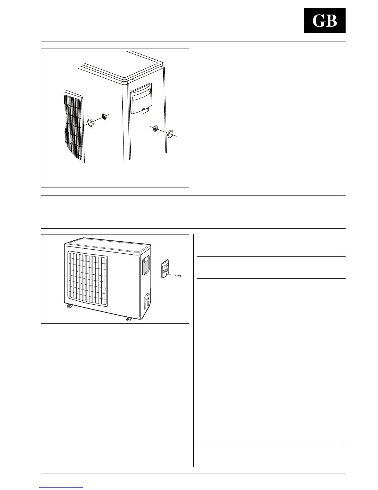
햲 Position for units size
005 - 007 - 009
햲
햳
햳 Position for units size
011 - 013
 Loading...