Do you have a question about the Carrier CNPVP, CNRVP and is the answer not in the manual?
Outlines signal words (DANGER, WARNING, CAUTION, NOTE) and general safety practices for installation.
Warning to turn off main power before installation to prevent electrical shock.
Alerts to personal injury risks from pressure release and sharp metal edges.
Introduces the CNPVP/CNRVP cased coils and their use in upflow/downflow furnaces.
Discusses airflow importance, TXV function, and cabinet sweating prevention.
Covers inspecting equipment upon arrival and selecting the correct installation method.
Details installing cased coils in upflow furnace configurations, including positioning.
Explains mounting standard and transition coils on narrow furnaces (Alternatives A, B, C).
Describes installing cased coils in downflow furnace configurations.
Outlines installing uncased coils in upflow furnaces using a support shelf.
Covers connecting refrigerant piping, liquid, suction lines, and brazing.
Details connecting the condensate drain line and trap, including overflow precautions.
Discusses considerations for installing a humidifier with the N-coil.
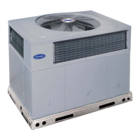
This document provides comprehensive installation instructions for CNPVP and CNRVP cased N-coils, designed for upflow and downflow heating and cooling applications. The manual emphasizes safety, proper installation techniques, and maintenance considerations to ensure optimal system performance and longevity.
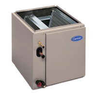
The CNPVP and CNRVP cased N-coils are integral components of heating and cooling systems, specifically designed to facilitate heat exchange. These coils are intended for use in upflow or downflow furnace configurations, but not in horizontal positions. CNPVP models are compatible with Puron (R-410A) refrigerant systems, while CNRVP models are designed for R-22 refrigerant systems. Both coil types come enclosed in a painted casing and are equipped with factory-installed Thermal Expansion Valves (TXVs). The primary function of these coils is to absorb heat from the indoor air during the cooling cycle and dissipate it during the heating cycle, thereby regulating indoor temperature and humidity.
The installation process for these coils is detailed, with specific instructions for various configurations. The manual highlights the importance of proper airflow, noting that inadequate airflow can lead to issues such as low system performance, restricted TXV operation, frosted coils, poor humidity control, and water blow-off. To mitigate these problems, installers are advised to ensure airflow rates of 350 to 400 cfm/ton during normal cooling operation.
For upflow installations, the coil is placed on the furnace discharge air opening. If the coil's front width matches the furnace's front width, it can be placed directly on the furnace. The coil must be level to ensure proper condensate drainage, and it should not be tipped toward the condensate drain. For installations in unconditioned spaces like garages or attics, a 6-inch (152 mm) wide piece of insulation should be wrapped around the coil casing and the supply duct connection point to prevent cabinet sweating.
Transition model coils applied centered over narrow furnaces do not require a separate transition. These coils are placed on top of the furnace with a 1 5/8-inch (41 mm) overhang on both sides. Standard model coils applied centered over narrow furnaces require a minimum 2 1/4-inch (57 mm) tall transition, which needs to be fabricated and secured with sheet metal screws. The coil is then placed on top of this transition, ensuring it rests evenly.
For downflow cased coil installations, the N-coil is placed on the supply duct opening. If the coil width matches the furnace width, the furnace can be placed directly on the cased coil. In downflow installations with a 4-way multipoise furnace, perforated duct flanges on the furnace should be broken off. Coils that under-hang (narrower than the furnace) require a 2 1/4-inch (57 mm) long field-fabricated transition. Coils that overhang (wider than the furnace) do not require a transition but necessitate a field-supplied furnace shelf to fit the furnace to the coil opening.
Uncased coil applications are possible for specific models marked with an asterisk (*) in the product table. For these models, the coil can be removed from its casing and installed as an uncased coil without needing to fabricate a coil enclosure to prevent air bypass. A coil support shelf must be field-fabricated using the provided dimensions and installed above the furnace duct flanges. A caution label, included with the installation instructions, must be affixed to the right side of the plenum enclosure to indicate slab location, especially when a humidifier is installed.
Refrigerant piping connections are critical. Installers must use accessory tubing packages or field-supplied refrigerant-grade tubing. It is crucial to avoid damaged, dirty, or contaminated tubing, as this can clog the refrigerant flow-control device. The coil and field-supplied tubing must always be evacuated before opening outdoor unit service valves. The suction line, designed for field sweat connection, is plugged to keep out moisture and dirt, and these plugs should only be removed when ready for connection.
Condensate drain line connections are designed to dispose of accumulated water. PVC fittings are recommended for the condensate pan, tightened finger-tight plus 1-1/2 turns. An unused condensate drain fitting must be plugged. If the unit is located in or above a living space where condensate overflow could cause damage, a field-supplied, external condensate pan should be installed under the entire unit, with a secondary condensate line draining to a noticeable place. Alternatively, a separate 3/4-inch (19 mm) condensate line with an appropriate trap can be run to a noticeable location. The homeowner must be informed that condensate flow from the secondary drain or external condensate pan indicates a need for servicing to prevent water damage. Installing a float switch to shut off the unit if water in the secondary pan gets too high is recommended for further protection. Traps should be installed in condensate lines as close to the coil as possible, ensuring the outlet of each trap is below its connection to the condensate pan to prevent overflow. All traps must be primed, tested for leaks, and insulated if located above a living area.
For humidifier applications, careful consideration must be given to the location of coil slabs to prevent damage to the N-coil when attaching the humidifier to the coil casing or plenum. The caution label indicating slab location is particularly important when these coils are removed from their casing and applied directly into the plenum.
The TXVs in both CNPVP and CNRVP models are factory-installed and have preset superheat settings that are not field-adjustable, simplifying maintenance by eliminating the need for on-site adjustments.
During brazing operations for refrigerant lines, it is essential to protect the TXV and nearby tubing with a heat-sinking material, such as a wet cloth, to prevent valve damage from overheating. Temperatures exceeding 212°F (100°C) can harm valve performance. A liquid filter dryer should be placed near the indoor unit to reduce the risk of debris clogging the valve, which can impact performance. The TXV bulb must be securely fastened and wrapped in the indentation on the vapor line tube.
When connecting refrigerant lines, a 1/2 psig Nitrogen purge should be used in the suction and out the liquid line. Brazing should be done using a Sil-Fos or Phos-copper alloy, avoiding soft solder. After brazing, joints should be allowed to cool, and rubber grommets should be slid over the joints, positioning the tubing at the center of each grommet to ensure an air seal. Lines must always be evacuated, and refrigerant reclaimed when making connections or flaring lines. Leak checks are mandatory before insulating the entire suction line. If the outdoor equipment is not installed immediately, the liquid and suction lines should be brazed closed outside, and a Schraeder port test fitting added to the suction line.
Regular inspection of the condensate drain lines and traps is necessary to ensure they are free of clogs and leaks. Priming traps and insulating them if located in unconditioned areas are part of routine maintenance to prevent issues. The instruction manual emphasizes the importance of consulting local codes for additional restrictions and precautions related to condensate disposal.
The caution label regarding coil slab location, especially for uncased coil installations and humidifier applications, serves as a permanent reminder for future service and installation technicians about critical component placement, aiding in efficient and safe maintenance.
Overall, the device is designed for reliable performance with clear guidelines for installation and maintenance, ensuring long-term operational efficiency and safety.
| Product Type | Heat Pump |
|---|---|
| Cooling Capacity | 18, 000 - 60, 000 BTU/h |
| Heating Capacity | 18, 000 - 60, 000 BTU/h |
| Refrigerant | R-410A |
| Power Supply | 208/230V |