3
8. Turn on power to unit. The thermostat will receive power
from the unit. The thermostat will be powered by 24 v,
nominal (18 to 30 vac). Terminal connections are R
(+ 24 v), O/W1 (first stage heat or reversing valve), Y1
(first stage cooling), and G (fan relay). Some applications
will use C (common), Y2 (second stage cooling), or W2
(second stage heating).
NOTE: The common (C) connection is not required on gas or
electric units with heating and cooling. The common (C) hook
up is required on heat pump applications and cooling or heat-
ing only units.
Table 1 — Thermostat Wiring Terminations
*Terminal C may not be used in all applications.
†Used on Heat Pump applications only.
**33CS250-FS only.
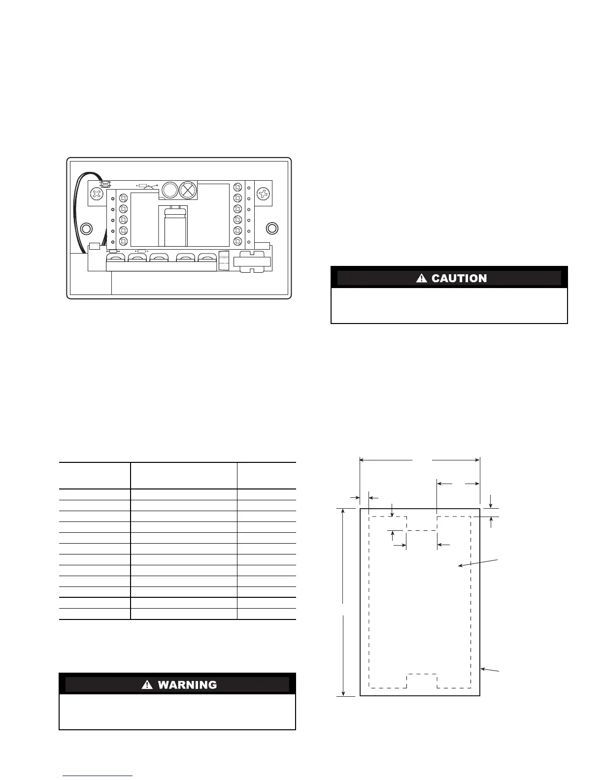
Install Thermostat (Without Junction Box)
1. Turn off all power to unit.
2. Using cutout template provided, cut hole into wall. See
Fig. 3.
a. If installing on dry wall, use outside of template to
mark hole on wall.
b. If installing on paneling, punch out inside of
template and use inside of template to mark hole
on wall.
3. Route thermostat wires through hole in wall. Remove
outer sheath from wires for added flexibility. Standard
solid or multi-conductor thermostat wire should be used
from the thermostat to the unit.
Size and length considerations are as follows: for a maxi-
mum wire distance from the unit of 36 ft, use 22 AWG
(American Wire Gage) wire; for a maximum distance
from the unit of 100 ft, use 18 AWG wire.
4. Adjust wire length and routing to allow proper fit of the
thermostat on the wall. Strip each wire at the end no more
than
1
/
4
-in. to prevent adjacent wires from shorting
together. Match and connect wires to terminals on the
thermostat. See Fig. 2 and Table 1.
5. Attach thermostat to wall.
On paneling installations (see Fig. 4):
a. Push thermostat into hole in wall. Make sure tabs
on paneling match up with mounting holes on
thermostat.
b. Using two 1
1
/
2
-in. self-tapping screws, attach
thermostat to wall. Make sure thermostat cover is
flush against wall and covers hole in wall.
EXISTING
WIRE
DESIGNATION
FUNCTION
TERMINAL
CONNECTION
GorF Fan G
Y1,Y,orC Cooling Y1
W1, W, or H Heating W1-O-B
Rh,R,M,Vr,orA Power (24 v) R
C Common C*
O/B Reversing Valve W1-O-B†
Y2 Second Stage Cooling Y2
W2 Second Stage Heating W2
RS+5 Remote Sensor (5 vdc) RS+5**
RS Remote Sensor Signal RS**
GND Remote Sensor Ground GND**
CK1 Dry Contact Switch CK1**
Before installing thermostat, turn off all power to unit.
There may be more than one power disconnect. Electrical
shock may cause injury or death.
Improper wiring or installation may cause damage to the
thermostat. Check to ensure wiring is correct before pro-
ceeding with installation of the thermostat.
CK1
GND
RS
RS+5
W2
Y2
C
G
Y1
R
W1-O-B
LEGEND
Fig. 2 — Thermostat Wiring (33CS250-FS Shown)
C—24 VAC Transformer Common
CK1 — Dry Contact Switch (33CS250-FS Only)
G—Fan
GND — Remote Sensor or Dry Contact Switch
Ground (33CS250-FS Only)
RS — Remote Sensor Signal (33CS250-FS Only)
RS+5 — Remote Sensor (+5 vdc) (33CS250-FS Only)
R—24 VAC Transformer Power
W1-O-B — First-Stage Heat or Reversing Valve
W2 — Second-Stage Heat
Y1 — First-Stage Compressor
Y2 — Second-Stage Compressor
PUNCH OUT
CENTER AND
USE INSIDE EDGE
FOR PANELING
INSTALLATIONS
USE OTHER EDGE
FOR DRY WALL
INSTALLATIONS
2 3/8”
7/8”
3/16”
9/16”
1/4”
3/16”
3 3/4”
Fig. 3 — Cutout Template
→
→
105
 Loading...