8
O/W2
W/W1
Y1/ W2
G
R
O
Y1
INDOOR CONTROL
FAN COIL
2-SPEED
HEAT PUMP
W1
G
W2
C
Y2
R
W1
Y1
O
C
DHUM
HUM
B
S1
S2
Y/Y2
R
C
DH
HEAT/COOL
STAGE 1
HEAT STAGE 3
HEAT/COOL
STAGE 2
RVS COOLING
FAN
24 VAC HOT
24 VAC COMM
DEHUMIDIFY
HUMIDIFY
RVS HEATING
OUTDOOR
SENSOR
CONNECTION
Y/Y2
HUMIDIFIER
(24 VAC)
OUTDOOR
SENSOR
REMOVE J2
JUMPER FOR
HEAT STAGING
REMOVE J1 FOR
DEHUMIDIFY
MODES
A02005
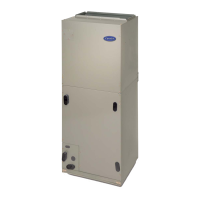
Fig. 12 -- FV4C Fan Coil Wiring with 2 --Speed Puron
(R-- 410A) Refrigerant Heat Pump
C. Intelligent Heat Staging Option
Intelligent Heat staging of the electric heat package is possible
when the FV4C is installed as a part of a single-- speed heat pump
system using a corporate 2 --speed programmable thermostat ,
Thermidistatt Control, or capable zoning control and any 1 of the
following electric heat packages:
Relay heaters
KFCEH2901N09, KFCEH3001F15, KFCEH3101C15,
KFCEH3201F20, KFCEH3301C20, KFCEH3401F24, or
KFCEH3501F30.
Complete system low--voltage wiring as shown in Fig. 9, 10, 11, or
12.
NOTE: Where local codes require thermostat wiring be routed
through conduit or raceways, splices can be made inside the fan
coil unit. All wiring must be NEC Class l and must be separated
from incoming power leads.
A factory --authorized disconnect kit is available for installation of
0-- through 10 --kW applications. When electric heat packages with
circuit breakers are installed, the circuit breaker can be used as a
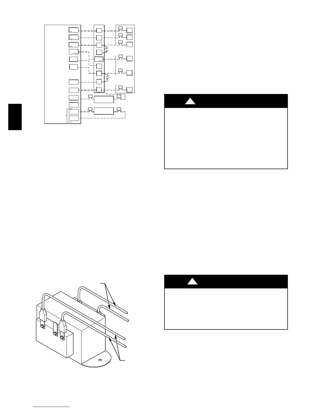
disconnect. Transformer is factory wired for 230--v operation. For
208--v applications, disconnect black wire from 230 --v terminal on
transformer and connect it to 208--v terminal. (See Fig. 13.)
230
C
208
BRN
RED
YEL
BLK
SECONDARY
PRIMAR
A05182
Fig. 13 -- Transformer Connections
The secondary circuit of transformer is protected by a 5--amp fuse
mounted on printed--circuit board.
IMPORTANT: Do not use outdoor thermostat with Intelligent
Heat Staging.
D. Manufactured Housing
In manufactured housing applications, the Code of Federal
Regulations, Title 24, Chapter XX, Part 3280.714 requires that
supplemental electric heat be locked out at outdoor temperatures
above 40_F(4_C) except for a heat pump defrost cycle. A
corporate thermostat in conjunction with an outdoor sensor can be
used to lock out supplemental heat above 40_F(4_C). Refer to
thermostat instructions for details. If a non --corporate thermostat is
used, an outdoor thermostat may be required.
E. Ground Connections
ELECTRICAL SHOCK HAZARD
Failure to follow this warning could result in personal injury
or death.
According to NEC, NFPA 70, and local codes, the cabinet
must have an uninterrupted or unbroken ground to minimize
personal injury if an electrical fault should occur. The ground
may consist of electrical wire or metal conduit when installed
in accordance with existing electrical codes. If conduit
connection uses reducing washers, a separate ground wire
must be used.
!
WARNING
NOTE: Use UL listed conduit and conduit connector to connect
supply wire(s) to unit and obtain proper grounding. Grounding
may also be accomplished by using grounding lug provided in
control box.
Use of dual or multiple supply circuits will require grounding of
each circuit to ground lugs provided on unit and heaters.
Pr ocedure 5 — REFRIGERANT TUBING
CONNECTION AND EVACUATION
Use accessory tubing package or field--supplied tubing of
refrigerant grade. Insulate entire suction tube if field--supplied
tubing is used. Tubing package has an insulated suction tube. Do
not use damaged, dirty , or contaminated tubing because it may
plug refrigerant flow control device.
When tubing package is used and sweat connections are made
within 60 sec, coil and tubing system does not require evacuation.
Always evacuate coil and field--supplied tubing to 500 microns
before opening outdoor unit service valves.
PRODUCT DAMAGE HAZARD
Failure to follow this caution may result in product or property
damage.
A brazing shield MUST be used when tubing sets are being
brazed to the unit connections to prevent damage to the unit
surface and condensate pan fitting caps.
CAUTION
!
Units have sweat suction and liquid tube connections. Make
suction tube connection first.
1. Cut tubing to correct length.
2. Insert tube into sweat connection on unit until it bottoms.
3. Braze connection using silver bearing or non--silver bearing
brazing materials. Do not use solder (materials which melt
below 800_F).
Consult local code requirements.
FV4C
 Loading...


